


CFW-09 -
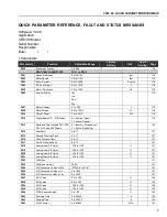
QUICK PARAMETER REFERENCE
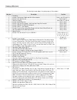
16
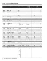
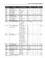
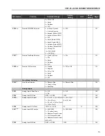
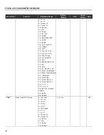
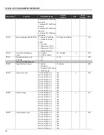
Parameters
Function
Adjustable Range
Factory
Unit
User's
Page
Setting
Setting
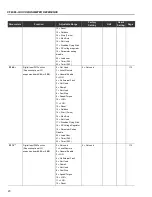
P239
(1)
Analog Input AI2 Signal
0 = (0 to 10) V / (0 to 20) mA 0 = (0 to 10) V /
-
166
1 = (4 to 20) mA
(0 to 20) mA
2 = (10 to 0) V / (20 to 0) mA
3 = (20 to 4) mA
P240
Analog Input AI2 Offset
-100.0 to +100.0
0.0
%
167
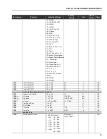
P241
(1) (8)
Analog Input AI3 Function
0 = P221/P222
0 = P221/P222
-
167
(Requires Optional I/O Expansion
1 = Without ramp
Board EBB)
2 = Maximum Torque Current
3 = PID Process Variable
4 = Maximum Torque Current
(AI3 + AI2)
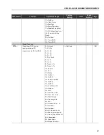
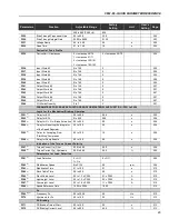
P242
Analog Input AI3 Gain
0.000 to 9.999
1.000
-
168
P243
(1)
Analog Input AI3 Signal
0 = (0 to 10) V / (0 to 20) mA 0 = (0 to 10) V /
-
168
1 = (4 to 20) mA
(0 to 20) mA
2 = (10 to 0) V / (20 to 0) mA
3 = (20 to 4) mA
P244
Analog Input AI3 Offset
-100.0 to +100.0
0.0
%
168
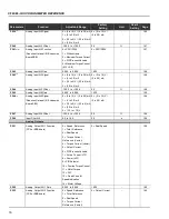
P245
Analog Input AI4 Gain
0.000 to 9.999
1.000
-
168
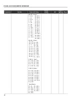
P246
(1)
Analog Input AI4 Signal
0 = (0 to 10) V / (0 to 20) mA 0 = (0 to 10) V /
-
168
(Requires Optional I/O Expansion
1 = (4 to 20) mA
(0 to 20) mA
Board EBA)
2 = (10 to 0) V / (20 to 0) mA
3 = (20 to 4) mA
4 = (-10 to +10) V
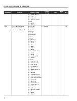
P247
Analog Input AI4 Offset
-100.0 to +100.0
0.0
%
169
P248
Input Filter AI2
0.0 to 16.0
0.0
s
169
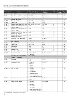
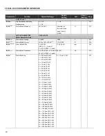
Analog Outputs
P251
Analog Output AO1 Function
0 = Speed Reference
2 = Real Speed
-
169
(CC9 or EBB board)
1 = Total Reference
2 = Real Speed
3 = Torque Current
Reference (Vector)
4 = Torque Current (Vector)
5 = Output Current
6 = PID Process Variable
7 = Active Current (V/F)
8 = Power (kW)
9 = PID Setpoint
10 = Positive Torque Current
11 = Motor Torque
12 = PLC
13 = Dead Zone for
Speed Indication
14 = Motor Voltage
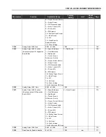
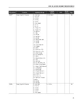
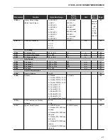
P252
Analog Output AO1 Gain
0.000 to 9.999
1.000
-
169
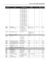
P253
Analog Output AO2 Function
0 = Speed Reference
5 = Output Current
-
169
(CC9 or EBB board)
1 = Total Reference
2 = Real Speed
3 = Torque Current
Reference (Vector)


