11.3
Connecting rod and piston
11.3.1 Description of connecting rod and piston
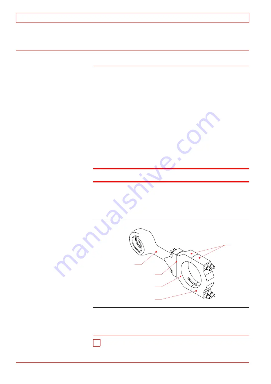
The connecting rod is of a three-piece design, so called “Marine
type connecting rod”. The combustion forces are distributed over
a maximum bearing area. The relative movements between mat-
ing surfaces are minimized.
The connecting rod is forged and machined of alloyed steel and splitted
horizontally in three parts to allow removal of piston and connecting rod
parts. All connecting rod bolts are hydraulically tightened.
The piston is of the composite type with an nodular cast iron skirt
and a forged steel crown screwed together. The space, formed between
the crown and the skirt, is supplied with lubricating oil for cooling of
the crown by means of the cocktail shaker effect. The lubricating oil is
led from the main bearing, through the drilling’s in the crankshaft, to
the big end bearing, and further through the drilling’s in the connecting
rod, gudgeon pin and piston skirt, up to the cooling space, and from
there back to the oil sump.
Note!
Always handle the pistons with care.
The piston ring set consists of two chrome-plated compression
rings and one spring-loaded oil scraper ring.
Connecting rod parts
11.3.2 Removing of piston and upper part of con-
necting rod for overhaul
1 Remove both crankcase covers
adjacent to the con-
necting rod concerned on both side of engine.
1
2
3
4
5
1. Connecting rod, upper part
2. Shim
3. Big end, upper half
4. Big end, lower half
5. Big end
Fig 11-2
4011019601
11
Crank Mechanism: Crankshaft, Connecting Rod, Piston
32-200020
11 - 4
WÄRTSILÄ 32
Содержание PAAE051728
Страница 4: ......
Страница 18: ...Appendix B Welding Precautions 200640 00 6...
Страница 26: ...01 Main Data Operating Data and General Design 32 200634 01 01 8 W RTSIL 32...
Страница 60: ...Appendix A Environmental Hazards 200507 02A 10...
Страница 68: ...Page 7 7 Document No 4V92A0645 Rev j...
Страница 84: ...03 Start Stop and Operation 32 200402 04 03 12 W RTSIL 32...
Страница 98: ...04 Maintenance Schedule 32 200623 01 04 14 W RTSIL 32...
Страница 154: ...07 Tightening Torques and Use of Hydraulic Tools 32 200643 01 07 30 W RTSIL 32...
Страница 162: ...08 Operating Troubles Emergency Operation 32 200402 01 08 8 W RTSIL 32...
Страница 164: ...Specific Installation Data 2005 01 09 2...
Страница 178: ...10 Engine Block with Bearings Oil Sump and Cylinder Liner 32 200150 10 14 W RTSIL 32 34SG...
Страница 216: ...Appendix A Testing of cylinder tightness 32 200142 A 4 W rtsil 20 32 34...
Страница 226: ...13 Camshaft Driving Gear 32 200546 02 13 10 W RTSIL 32...
Страница 253: ...U tube manometer Fig 15 12 401508200050 32 200549 10 Turbocharging and Air Cooling 15 W RTSIL 32 15 19...
Страница 254: ...15 Turbocharging and Air Cooling 32 200549 10 15 20 W RTSIL 32...
Страница 274: ...16 Injection System 32 200627 01 16 20 W RTSIL 32...
Страница 280: ...Fuel System 32 200508 07 17 6 W RTSIL 32...
Страница 314: ...19 Cooling Water System 32 200050 19 14 W RTSIL 32...
Страница 394: ...23 Instrumentation and Automation 32 200115 II 23 60 W RTSIL 32...


