20. Exhaust System
20.1
Exhaust manifold
20.1.1 General description
Data and dimension
Multiduct
Material:
Nodular cast iron
Weight:
60 kg
Test pressure:
10 bar
(water side)
Exhaust pipes
Material: Special, heat resis-
tant alloy nodular cast iron
Bellows
Multiply design
Material: Heat resistant steel
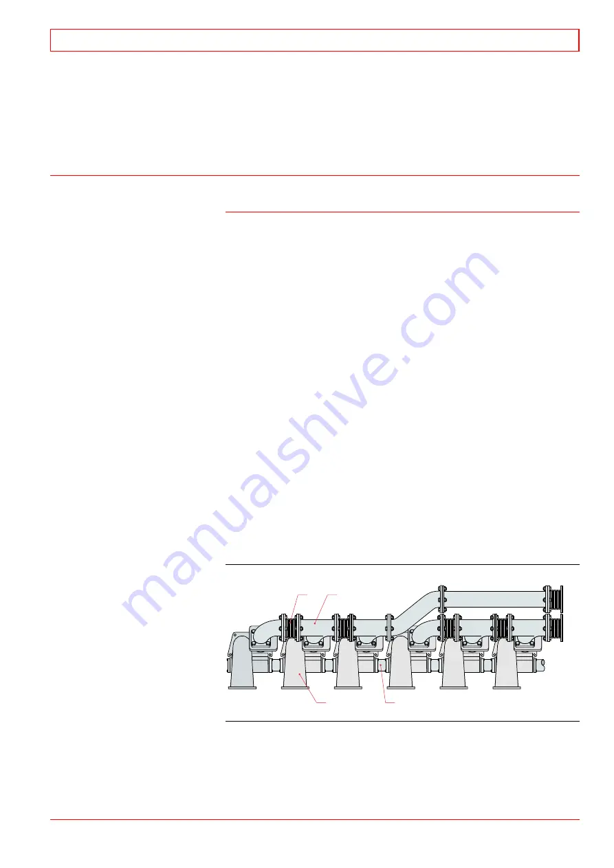
The exhaust manifold is fitted between the cylinder head and the
turbocharger. The manifold consists of the multiducts (3) and the
exhaust pipes (2) with expansion bellows (1). The manifold is
enclosed into an insulating box of sandwich design.
The turbocharging concept depends on the type of installation,
alternatively a specific type of pulse charging or a constant
pressure charging are used. The exhaust gases connected to one
pipe are discharged from each cylinder during the period when
the other cylinders connected to the same pipe have the exhaust
valve closed. This gives an equal flow of gases to the turbocharger
without any disturbing gas pulses to the other cylinders connected
to the common pipe.
The multiduct, between the cylinder head and the exhaust
pipes, acts as a bracket for the whole exhaust manifold, including
the insulation box. The multiduct is cooled by the cooling water
discharging from the cylinder head. The multiducts are vented
through a venting pipe along the engine. The cooling water flows
from the multiducts (3) through the water pipes (4) in the cooling
water box. The multiduct also connects the air receiver in the
engine block with the inlet air channel in the cylinder head. All
the surfaces, engine block/multiduct, cylinder head/ multiduct
and exhaust pipes/multiduct are sealed off.
Exhaust manifold
The multiduct is rigidly mounted towards the cylinder head.
The exhaust pipes are cast of special alloy nodular cast iron,
with separate sections for each cylinder. Metal bellows of multiply
type absorb the heat expansion.
1. Bellows
2. Exhaust gas pipe
3. Multiduct
4. Water pipe
1
3
2
4
Fig 20-1
4020019601
32-200045
Exhaust System
20
WÄRTSILÄ 32
20 - 1
Содержание PAAE051728
Страница 4: ......
Страница 18: ...Appendix B Welding Precautions 200640 00 6...
Страница 26: ...01 Main Data Operating Data and General Design 32 200634 01 01 8 W RTSIL 32...
Страница 60: ...Appendix A Environmental Hazards 200507 02A 10...
Страница 68: ...Page 7 7 Document No 4V92A0645 Rev j...
Страница 84: ...03 Start Stop and Operation 32 200402 04 03 12 W RTSIL 32...
Страница 98: ...04 Maintenance Schedule 32 200623 01 04 14 W RTSIL 32...
Страница 154: ...07 Tightening Torques and Use of Hydraulic Tools 32 200643 01 07 30 W RTSIL 32...
Страница 162: ...08 Operating Troubles Emergency Operation 32 200402 01 08 8 W RTSIL 32...
Страница 164: ...Specific Installation Data 2005 01 09 2...
Страница 178: ...10 Engine Block with Bearings Oil Sump and Cylinder Liner 32 200150 10 14 W RTSIL 32 34SG...
Страница 216: ...Appendix A Testing of cylinder tightness 32 200142 A 4 W rtsil 20 32 34...
Страница 226: ...13 Camshaft Driving Gear 32 200546 02 13 10 W RTSIL 32...
Страница 253: ...U tube manometer Fig 15 12 401508200050 32 200549 10 Turbocharging and Air Cooling 15 W RTSIL 32 15 19...
Страница 254: ...15 Turbocharging and Air Cooling 32 200549 10 15 20 W RTSIL 32...
Страница 274: ...16 Injection System 32 200627 01 16 20 W RTSIL 32...
Страница 280: ...Fuel System 32 200508 07 17 6 W RTSIL 32...
Страница 314: ...19 Cooling Water System 32 200050 19 14 W RTSIL 32...
Страница 394: ...23 Instrumentation and Automation 32 200115 II 23 60 W RTSIL 32...


