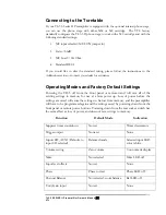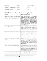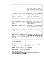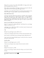
Status:
The unit is completely off and cannot be turned on via any front
panel or remote command.
2. Stand-by Mode
Unit is left in standby and waiting power up command when not operated. No circuits
are running, except logic circuit to power control microprocessor.
User input:
AC power is connected to the preampand rear rocker switch is
switched to ON position.
Indication:
The numeric display displays a steady double-dash.
Status:
Processor waits for power on command from either front panel,
remote control wand, or discrete remote command from external
remote (Crestron or AMX) via rear RS-232 port.
3. Power up mode (Remote control or front panel)
Unit is required for use.
User input:
Unit is in standby mode and user presses the Power button, either
on the front panel or the remote control, or sends a discrete power
on signal from external remote.
Indication:
The power-on LED on the unit blinks to indicate that the power on
sequence is being executed. At the same time, (if not suppressed by
user) the numeric display goes into the sequential countdown timer
from 90 to 0. If power on sequence is successfully executed, display
on unit indicates that it is no longer in standby mode when the
numeric display changes to 0.
When the unit has completed the power-up sequence, the numeric
display changes to volume indicator to indicate that unit is now
ready to play, and the volume readout shows 0. The front panel
LED for last input selected is lit, and power LED is steady blue.
Status:
Unit is in zero volume mute mode, last used input is selected,
balanced/single-ended mode and unity gain processor loop settings
for all inputs are restored. The last phase setting and channel balance
since the last power-off are also restored. The unit is ready to go into
play mode after the user increments the volume.
4. User unlocks Programming Lockout (During power-up only) (Front panel or RS-232
port)
Programming lockout is to lock all programming functions so that they are not able to
be accidentally re-set to some unintended setting during normal operation. (To make a
system change requiring re-programming, lockout is unlocked and then re-locked after
making the change.)
TL5.5 SERIES II Preamplifier Owner’s Manual
VTL
26
Содержание TL5.5 Series II Signature
Страница 1: ...VTL TL5 5 Series II Signature Preamplifier Owner sManual...
Страница 3: ......

