•
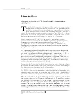
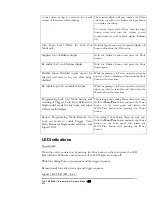
When in volume control mode the control knob changes the loudness level
of the output from your speaker system. Turning the knob clockwise
increases the volume level, and turning the knob counter-clockwise decrease s
the volume level.
The Preamplifier’s Back Panel
From the back panel of the chassis you can access the power connector, trigger outputs,
RS-232 port, AC fuse, and the serial number and power consumption of the unit, as well
as all of the audio inputs and outputs.
Fig. 2 Rear Panel
Back Panel Connections and controls
The
Power Receptacle i
s used for connecting the TL5.5 to the AC power from a wall outlet
using the power cord.
The
Main Fuse Holder
contains the main power fuse.
CAUTION: Replace fuses only
with fuses of same type and rating.
The
Power Rocker
powers the unit into standby mode. Press up for on and down for off.
The
Trigger Outputs
provide a 12V DC signal to external components that are to remotely
power up after the preamplifier is operational. Connect the power amplifiers’ trigger inputs
to the TL5.5’s
Trigger Outputs
to remotely power the amplifier(s) on and off.
The
Information labe
l contains Serial number, AC voltage setting and power consumption
information.
The
RCA
and
XLR Input Jacks.
2 pairs of single-ended/balanced line inputs to connect source components to the
preamplifier section of the TL5.5, including CD, Aux 1.
5 single-ended RCA inputs Ph/Aux 2, Aux 3, Tuner, Aux 4 and Aux 5
1 pair of single ended RCA Tape input
The
RCA
and
XLR Output Jacks.
TL5.5 SERIES II Preamplifier Owner’s Manual
VTL
10
Содержание TL5.5 Series II Signature
Страница 1: ...VTL TL5 5 Series II Signature Preamplifier Owner sManual...
Страница 3: ......

