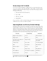
5. The
display window
contains the group of three main operational buttons and display
LEDs, the numeric display, and the infra-red remote receiver, which enables the
transmission of signal from the remote hand-held unit to be received by the
preamplifier. Keep this window clear from any obstruction and out of direct light to
allow maximum signal transmission from the remote wand.
The three main operational buttons are:-
a) The
Phase
button allows you to switch the system into the phase reversed state.
•
Pressing the
Phase
button toggles the system between the Phase 0 and Phase
180 (inverted) states. The
Phase
LED will turn off when the system is in Phase
0 state, and will be steady red in the phase inverted state.
b) The
Balance
button allows the user to change the channel balance setting between
left and right channel.
•
Select the
Balance
button changes the display to the balance display and sets
the
Balance
LED to blue. While the display is indicating “—“, turn the rotary
knob changes balance from left to right, according to the direction of
rotation. In this mode the control knob is used to set the left and right
channel level.
In the
Balance
mode, when the display shows a double dash this indicates that
the left and right channels are equally balanced. A number with a bar on either
side indicates an out of balance setting, with the bar indicating the direction of
balance and the display indicating the degree of out of balance.
The display automatically reverts to volume readout a few seconds after
release of the
Balance
button.
c) The
Mute
button is to allow the user to switch the preamplifier into the muted
state.
Pressing the button toggles the system between the muted and operating
states. If the preamplifier is currently in the operating state, pressing the
Mute
button will set the unit to the muted state, indicated by a flashing red
Mute
LED. If the preamplifier is currently in mute state, pressing the
Mute
button will change the system into the operating state, and the LED will
turn off.
The
Numeric
display is used to indicate either the sequential countdown timer during
power-up, offset level of the selected input, channel balance offset, trigger timing
during trigger output programming (during power up only), and the overall volume
gain level setting.
6. The
Control knob
is used in conjunction with the
Numeric Display
for setting volume
gain level in the operate mode, or when in one of the programming modes (trigger
programming, channel balance setting or input offset programming mode) the control
knob is used to dial in the appropriate setting.
TL5.5 SERIES II Preamplifier Owner’s Manual
VTL
9
Содержание TL5.5 Series II Signature
Страница 1: ...VTL TL5 5 Series II Signature Preamplifier Owner sManual...
Страница 3: ......

