8
HDR-5000 User and Technical Manual
2.4 Installing the HDR-5000
The HDR-5000 is typically mounted in a standard 19-inch (48.3 cm) rack. Each unit occupies 2 rack units
(2RU) of height. The cabling is permanently installed and power comes from the facility or site power
source. This section describes typical mounting and cabling for the HDR-5000; your installation may vary.
WARNING
Follow instructions carefully. Do not place the equipment on an unstable support
such as a cart, stand, or table. The equipment could fall and cause equipment
damage or cause personal injury.
Mounting the HDR-5000 receiver into an equipment rack is easier if one person holds the unit while
another person installs the mounting screws. Do the following to set up the components at each receive
site.
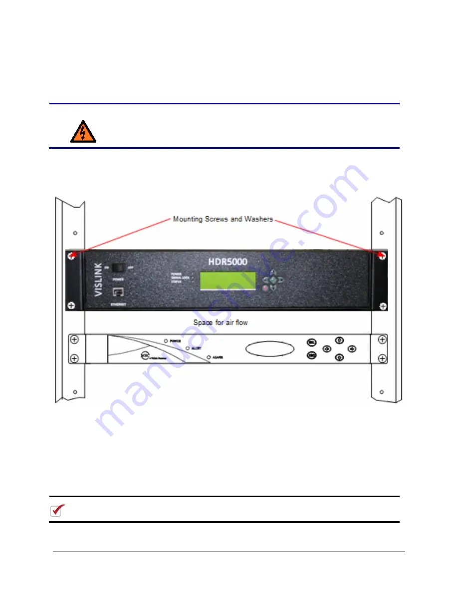
Figure 2-1. Mounting the HDR-5000 Rear Panel (HDR-5000-1/2 model shown)
1. Line up the mounting holes on the receiver front panel with the mounting holes on the rack as
shown in the figure.
2. Install the two bottom screws first. Use lock washers to prevent loosening and be sure that the
fasteners tightened securely.
3. Install the top two screws. Use lock washers to prevent loosening. Tighten securely.
4. Make
sure
the
POWER
switch is off (
O
). Connect the standard 3-prong power cable to the back
of the HDR-5000 then connect the other end to the AC power source. An auto-sense circuit
accepts either 105 to 130 VAC or 205 to 240 VAC, 47 to 63 Hz.
NOTE:
When installing components, leave 1 RU of space between them for ventilation.
Also, for non-US applications, you must replace the 3-prong male connector.
Содержание HDR-5000
Страница 6: ......


