background image

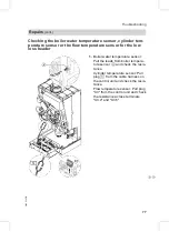
Checking the boiler water temperature sensor, cylinder tem-
perature sensor or the flow temperature sensor for the low
loss header

1.

Boiler water temperature sensor:
Pull the leads from boiler tempera-
ture sensor

A

and check the resis-

tance.
Cylinder temperature sensor: Pull
plug

%

from the cable harness on

the control unit and check the resis-
tance.
Flow temperature sensor: Pull plug
"X3" from the control unit and check
the resistance across terminals
"X3.4" and "X3.5".

Repairs

(cont.)

77

Troubleshooting

5692

536

GB

Содержание Vitoplus 300

Страница 1: ...us 300 Type VP3A 12 9 19 3 kW 16 1 23 5 kW Wall mounted oil fired condensing boiler for the combustion of low sulphur fuel oil DIN 51603 EL 1 with integral boiler control unit For applicability see the last page VITOPLUS 300 5692 536 GB 7 2005 Please keep safe ...

Страница 2: ...l legal instructions regarding the prevention of accidents all legal instructions regarding environmental protection the Code of Practice of relevant trade associations all current safety regulations as defined by DIN EN DVGW TRGI TRF VDE and all locally applicable standards If you smell gas Danger Escaping gas can lead to explosions which may result in serious injury Never smoke Prevent naked fla...

Страница 3: ...c loads Repair work Please note Repairing components which fulfil a safety function can com promise the safe operation of your heating system Replace faulty components only with original Viessmann spare parts Ancillary components spare and wearing parts Please note Spare and wearing parts which have not been tested together with the heating system can compromise its function Instal ling non author...

Страница 4: ...sensors 64 Troubleshooting Fault display 67 Calling up fault codes from the fault memory fault history 68 Fault codes 68 Repairs 75 Function description Control 85 Extensions for external connections accessories 89 Control functions 91 Remote control DIP switch 97 Designs Connection and wiring diagrams internal connections 98 Connection and wiring diagrams external connections 99 Parts lists 101 S...

Страница 5: ...nd checking the vacuum 13 11 Adjusting the air volume static burner pressure 14 12 Cleaning and testing the flame monitor 16 13 Cleaning the burner 17 14 Adjusting or replacing the nozzle and checking the ignition electrodes 18 15 Cleaning and replacing the oil pump filter if required 20 16 Checking the heating surfaces for contamination 21 17 Cleaning the heating surfaces 22 18 Checking the conde...

Страница 6: ...s 25 Checking the tightness of electrical connections 26 Matching the control unit to the heating system 24 27 Integrating the control unit into the LON system 30 28 Implementing a user check in conjunction with the LON system 31 29 Adjusting heating curves 32 30 Instructing the system user 36 31 Scanning and resetting the Maintenance display 36 Steps initial start up inspection and cont 6 Initial...

Страница 7: ... to the fill water Drain the heating system via boiler fill drain valve A minimum sys tem pressure 0 8 bar Note If the control unit has not been switched ON prior to filling the sys tem then the servomotor of the changeover valve will still be in its central position and the system will be completely filled 3 If the control unit had already been switched ON before filling began Start the control u...

Страница 8: ...er side 2 Connect the drain hose between top valve B and a drain outlet 3 Open valves A and B and vent at mains pressure until no sound of escaping air can be heard 4 Close valves A and B and open the primary shut off valves Further details regarding the individual steps cont 8 Initial start up inspection maintenance 5692 536 GB ...

Страница 9: ...ck the system pressure Filling the siphon with water 1 Remove the retaining clip and siphon A 2 Fill the siphon with water 3 Fit siphon A and secure with the retaining clip Setting the time and date if required Note During commissioning or after prolonged time out of use it may be necessary to set the time and date if the time flashes in the display 1 Set the correct time with a b 2 Confirm with d...

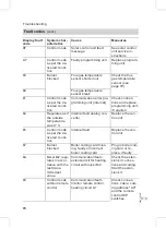
Страница 10: ... 68 Display screen Measures Control unit is sues heat de mand No Increase set value and ensure heat is drawn off Yes Oil pre heating starts No after approx 10 min Check the oil pre heater cables and plug in con nections Fault E6 Yes The fan starts after max 10 min No Fault Check the oil pre heater fan cables and plug in connections the oil preheater has not switched through the tem perature is not...

Страница 11: ...ault Check the oil sup ply check the so lenoid valves F4 Yes Flame signal pre sent Symbol A No Fault Checking the flame monitor F4 Yes Burner in opera tion Adjusting the standard burner settings Standard burner settings Note Check that the service instructions are valid for the relevant burner see applic ability on the last page and the serial no on the boiler type plate Further details regarding ...

Страница 12: ...e kg h 1 05 1 58 1 31 1 92 approx l h 1 24 1 86 1 57 2 30 Static burner pres sure approx Operating phase Ignition phase mbar mbar 8 0 9 5 11 16 0 17 5 11 8 7 10 7 11 17 5 19 5 11 CO2 content ap prox Test value excl cap panel 12 2 13 0 12 2 13 0 Test value incl cap panel 12 7 13 5 12 7 13 5 Flame monitor set ting 5 5 Nozzle gap a mm 3 0 0 2 0 3 1 5 0 2 0 3 Further details regarding the individual s...

Страница 13: ...nto test port P A and the vacuum gauge range 0 1 bar into test port V B Note Seal the pressure and vacuum gauges only with copper or alumi nium gaskets or with O rings Never use tape to seal these joints 2 Start the boiler 3 Press K and d simultaneously for approx 2 s Relay test is shown in the dis play 4 Select burner stage 1 with a and b Burner st 1 ON is shown on the display 5 Where vacuum meas...

Страница 14: ...values after adjusting the oil pressure 11 After testing press d Adjusting the air volume static burner pressure 1 Start the boiler 2 Remove plug A from the test port 3 Connect the U shaped pressure gauge to test port A 4 Press K and F simultaneously until Speed stage 1 and a value between 1 and 255 is displayed 5 Change the value with a b until the static burner pressure dis played on the U shape...

Страница 15: ... 1 2 and a value between 1 and 255 7 Repeat steps 4 and 5 for burner stage 2 8 Check the set values 9 Seal test connector A again with the previously removed plug Note Do not seal the connector next to test connector A Further details regarding the individual steps cont 15 Initial start up inspection maintenance 5692 536 GB ...

Страница 16: ...e safety period TSA 2 Start the burner with the flame monitor ex posed to exter nal light Fault shutdown after a max of 40 s 3 Burner opera tion with simu lated flame blow off For this cover the flame monitor during opera tion and leave in that state Restart followed by a fault shut down at the end of the safety per iod TSA 3 Fit the flame monitor Further details regarding the individual steps con...

Страница 17: ...nce position 2 Pull the leads off ignition electro des B 3 Undo Allen screw C and remove rifling facility D 4 Clean the restrictor metering ring ignition electrodes and the flame monitor tube Further details regarding the individual steps cont 17 Initial start up inspection maintenance 5692 536 GB ...

Страница 18: ...zzle and checking the ignition electrodes 1 Undo nozzle E whilst holding the oil preheater Prevent the forma tion of bubbles Further details regarding the individual steps cont 18 Initial start up inspection maintenance 5692 536 GB ...

Страница 19: ...illed holes towards the cable entries Install the oil burner nozzle cen trally in the restrictor 4 Secure Allen screw C of the rifling facility Check nozzle gap a Please note An incorrectly adjusted noz zle gap a can result in irre gular operation of the burner and even a fault shutdown Rated output kW 12 9 19 3 16 1 23 5 Nozzle gap a see page 18 mm 3 0 0 2 0 3 1 5 0 2 0 3 Further details regardin...

Страница 20: ...g the oil pump filter if required Oil pump make Danfoss type BFP 52 A Filter plug B O ring replace C Filter replace Further details regarding the individual steps cont 20 Initial start up inspection maintenance 5692 536 GB ...

Страница 21: ... on the l h side of the boiler 2 Pull the flame monitor from the burner retainer 3 Insert burner retainer A part of the cleaning set into the l h side of the boiler 4 Undo four nuts from burner B and remove the burner Further details regarding the individual steps cont 21 Initial start up inspection maintenance 5692 536 GB ...

Страница 22: ...er Cleaning the heating surfaces Please note To prevent damage to the heat ing surfaces only clean with the implements supplied as part of the optional cleaning set 1 Pull condensate drain hose C from the neutralising system and lead it into a suitable vessel Further details regarding the individual steps cont 22 Initial start up inspection maintenance 5692 536 GB ...

Страница 23: ...roughly flush the combustion chamber with water Ensure that the drain hose continues to termi nate in the vessel see points 1 Checking the condensate drain and cleaning the siphon 1 Check at siphon A that the con densate can freely drain off 2 Remove the retaining clip and the siphon 3 Clean the siphon 4 Fill siphon A with water and fit it to the boiler Position the retaining clip Checking the neu...

Страница 24: ...t level the control unit must be matched to the system Various system components are recognised automatically by the control unit and the relevant codes are adjusted automatically For the selection of an appropriate design see the following diagrams For coding steps see page 38 System design 1 With without DHW heating with one heating circuit without mixer A1 Outside temperature sensor Cylinder te...

Страница 25: ...reater than the volume flow of the heating circuit with mixer Outside temperature sensor Flow temperature sensor Cylinder temperature sensor sÖ Heating circuit pump aVG KM BUS aBH Power supply extension kit A Maximum thermostat underfloor heating B Extension kit for a heating circuit with mixer Further details regarding the individual steps cont 25 Initial start up inspection maintenance 5692 536 ...

Страница 26: ...re sensor Flow temperature sensor Cylinder temperature sensor sÖ Heating circuit pump aVG KM BUS aBH Power supply extension kit A Maximum thermostat underfloor heating B Extension kit for a heating circuit with mixer C Heat exchanger for system separation Further details regarding the individual steps cont 26 Initial start up inspection maintenance 5692 536 GB ...

Страница 27: ...r Cylinder temperature sensor sÖ Heating circuit pump aVG KM BUS aBH Power supply extension kit A External extension H1 B Maximum thermostat underfloor heating C Extension kit for a heating circuit with mixer Required coding Address Max speed of the internal circulation pump in heating mode 20 31 20 Further details regarding the individual steps cont 27 Initial start up inspection maintenance 5692...

Страница 28: ... circuit pump aVG KM BUS aBH Power supply extension kit A Extension kit for a heating circuit with mixer B Vitotronic 050 C Maximum thermostat underfloor heating Required coding Address One heating circuit with mixer with extension kit for mixer and one heating circuit with mixer with the Vitotronic 050 with DHW cylinder 00 4 without DHW cylinder 00 3 Further details regarding the individual steps...

Страница 29: ...for Vitosolic 100 accessories E Cylinder temperature sensor for solar operation F Cylinder temperature sensor accessories G High limit safety cut out 1 H Re stratification pump Further details regarding the individual steps cont 29 Initial start up inspection maintenance 5692 536 GB 1High limit safety cut out required only for 1DHW volume smaller than 30 l m2 absorber surface when using the Vitoso...

Страница 30: ...nnot be allocated twice Updating the LON user list Only possible if all users are connected and the control unit is programmed to be fault manager code 79 1 1 Press L and d simultaneously for approx 2 s User check has been initiated see page 31 2 Press e The user list is updated after approx 2 min The user check is completed Single boiler system with Vitotronic 050 and Vitocom 300 Boiler control u...

Страница 31: ...ia LON Set Code 97 1 The outside tem perature is received via LON Set Code 97 1 Implementing a user check in conjunction with the LON sys tem Communication with the system devices connected to the fault manager is tested with a user check Preconditions The control unit must be programmed as fault manager code 79 1 The LON user number must be programmed in all control units see page 30 The fault ma...

Страница 32: ...between both devices Check the LON connection 4 For checking further users proceed as described under items 2 and 3 5 Press L and d simultaneously for approx 1 s The user check is completed Adjusting heating curves The heating curves illustrate the rela tionship between the outside tem perature and the boiler water or the flow temperature To put it simply The lower the outside temperature the high...

Страница 33: ...he heating curve lies in the range of A for underfloor heating systems in the range of B for low tempera ture heating systems according to the Energy Savings Order Ger many Further details regarding the individual steps cont 33 Initial start up inspection maintenance 5692 536 GB ...

Страница 34: ...e 38 Adjustable value from 13 to 40 K Adjusting the set room temperature Standard room temperature 1 In case of two heating circuits select the relevant one Press a 1r flashes on the display Select heating circuit A1 heating circuit without mixer Press d Select heating circuit with mixer M2 Press a 2r flashes on the display Press d Further details regarding the individual steps cont 34 Initial sta...

Страница 35: ... the heating curve is adjusted along set room tempera ture axis C which results in modi fied start stop characteristics of the heating circuit pumps if the heating circuit pump logic is enabled Reduced room temperature 1 In case of two heating circuits select the relevant one Press a 1r flashes on the display Select heating circuit A1 heating circuit without mixer Press d Select heating circuit wi...

Страница 36: ... the system user and instruct him her in the operation of the system Scanning and resetting the Maintenance display The red fault indicator flashes when the limits set via coding address 21 and 23 have been reached The programming unit display flashes Maintenance Note Set code 24 1 and then code 24 0 if a service is carried out before mainte nance is displayed the set maintenance parameters for ho...

Страница 37: ...ayed by pressing d approx 3 s After maintenance has been carried out 1 Reset code 24 1 to 24 0 The red fault indicator extin guishes Note If the coding address 24 is not reset a new Maintenance display will be shown on Monday at 07 00 h 2 If required Press c Reset burner hours run burner starts and consumption see page 64 Press c Further details regarding the individual steps cont 37 Initial start...

Страница 38: ...ayed as plain text Codes which are irrelevant due to the system equipment level or the setting of other codes will not be displayed 3 Change the value with a or b confirm with d The display briefly shows Accepted then the address flashes again Any address may be selected with a or b 4 Press K and L simultaneously for approx 1 s Encoding has been terminated Code 1 38 Coding 5692 536 GB ...

Страница 39: ...ystem design 2 3 4 1 heating circuit without mixer A1 and 1 heating circuit with mixer M2 without DHW heating 00 6 System design 2 3 4 1 heating circuit without mixer A1 and 1 heating circuit with mixer M2 with DHW heating Max boiler temp 06 Maximum limit of the boiler water tempera ture defaulted by the boiler coding card 06 20 to 06 127 Maximum limit of the boil er water temperature within the r...

Страница 40: ...p A1 C5 20 Electronic minimum flow temperature limit 20 C C5 1 to C5 127 Minimum limit adjustable from 1 to 127 C Min flow temp M2 C5 20 Electronic minimum flow temperature limit 20 C C5 1 to C5 127 Minimum limit adjustable from 1 to 127 C Max flow temp A1 C6 75 Electronic maximum flow temperature limit set to 75 C C6 1 to C6 127 Maximum limit adjustable from 1 to 127 C Max flow temp M2 C6 75 Elec...

Страница 41: ... and G simultaneously for approx 2 s confirm with d 2 Select the required coding address with a or b the address flashes Confirm with d the value flashes 3 Change the value with a or b confirm with d The display briefly shows Accepted then the address flashes again Any address may be selected with a or b 4 Press L and G simultaneously for approx 1 s Encoding has been terminated Complete overview T...

Страница 42: ... to Fb Note Codes which are irrelevant due to the system equipment level or the setting of other codes will not be displayed For heating systems with one heating circuit without mixer and one heating cir cuit with mixer initially the available coding addresses A0 to Fb are scrolled for the heating circuit without mixer A1 then those for the heating circuit with mixer M2 Code 2 cont 42 Coding 5692 ...

Страница 43: ...M2 without DHW heating 00 6 System design 2 3 4 1 heating circuit without mixer A1 and 1 heating circuit with mixer M2 with DHW heating Boiler burner 06 Maximum limit of the boiler water tempera ture defaulted by the boiler coding card 06 20 to 06 127 Maximum limit of the boil er water temperature within the ranges de faulted by the boiler 21 0 No maintenance indica tion Burner 21 1 to 21 100 The ...

Страница 44: ...2E 1 With external extension automatic adjustment on connection 2F 0 Venting program filling program disabled 2F 1 Venting program enabled 2F 2 Filling program enabled 30 1 Internal variable speed circulation pump auto matic adjustment 30 0 Internal circulation pump without variable speed e g temporarily for ser vice 31 65 Set speed of internal circulation pump when operated as boiler cir cuit pum...

Страница 45: ...6 Control funct OFF OFF Control funct 7 Control funct OFF OFF OFF 8 OFF Control funct Control funct Control funct 9 OFF Control funct Control funct OFF 10 OFF Control funct OFF Control funct 11 OFF Control funct OFF OFF 12 OFF OFF Control funct Control funct 13 OFF OFF Control funct OFF 14 OFF OFF OFF Control funct 15 OFF OFF OFF OFF Coding in the delivered condition Possible change Boiler burner ...

Страница 46: ... 5 Control funct OFF Control funct OFF 6 Control funct OFF OFF Control funct 7 Control funct OFF OFF OFF 8 OFF Control funct Control funct Control funct 9 OFF Control funct Control funct OFF 10 OFF Control funct OFF Control funct 11 OFF Control funct OFF OFF 12 OFF OFF Control funct Control funct 13 OFF OFF Control funct OFF 14 OFF OFF OFF Control funct 15 OFF OFF OFF OFF 16 ON Control funct Contr...

Страница 47: ...ure ad justable from 10 to 60 C 56 1 DHW temperature adjus table from 10 to above 60 C max value subject to boiler coding card Observe the max per missible DHW tempera ture 58 0 Without auxiliary func tion for DHW heating 58 10 to 58 60 Input of a second set DHW value adjustable from 10 to 60 C 59 0 Cylinder heating Starting point 2 5 K Stopping point 2 5 K 59 1 to 59 10 Starting point adjustable ...

Страница 48: ... to 6C 100 Set speed adjustable from 0 to 100 6F 100 Maximum output for DHW heating 100 de faulted by the boiler coding card 71 0 DHW circulation pump ON according to DHW time program separate switching times are possible for Vitotrol 300 71 1 OFF during DHW heating to set value 1 71 2 ON during DHW heating to set value 1 72 0 DHW circulation pump ON according to DHW time program 72 1 OFF during D...

Страница 49: ...ay for fault message message will be issued if a fault persists for at least 5 seconds 80 0 Without time delay 80 2 to 80 199 Time delay adjustable from 10 to 995 1 step 5 s 81 1 Automatic summer win ter time changeover 81 0 Manual summer winter time changeover 81 2 The radio clock module will be recognised auto matically 81 3 Accept time via LON 88 0 Temperature displayed in Celsius 88 1 Temperat...

Страница 50: ...com munication interface automatic recognition 97 0 The outside tempera ture of the sensor con nected to the control unit is utilised internally 97 1 The outside temperature is accepted by the LON BUS 97 2 The outside temperature of the sensor connected to the control unit will be utilised internally and is transmitted via the LON BUS to any connected Vitotronic 050 98 1 Viessmann system number in...

Страница 51: ...er circuit mixer circuit A0 0 Without remote control A0 1 With Vitotrol 200 auto matic recognition A0 2 With Vitotrol 300 auto matic recognition A3 2 Outside temperature below 1 C Heating cir cuit pump ON Outside temperature above 3 C Heating cir cuit pump OFF Note When selecting a value below 1 C there is a risk of pipes outside the thermal envelope of the building being damaged by frost The stan...

Страница 52: ...Possible change Boiler circuit mixer circuit A4 0 With frost protection A4 1 No frost protection this setting is only possible if code A3 9 has been selected Note When selecting a value below 1 C there is a risk of pipes outside the ther mal envelope of the building being damaged by frost The standby mode in particular should be taken into con sideration e g during holidays Code 2 cont 52 Coding 5...

Страница 53: ...set AT RTset 1 K A5 0 Without heating circuit pump logic function A5 1 to A5 15 With heating circuit pump logic function Heating circuit pump OFF if see the following table Parameter address A5 With heating circuit pump logic function Heating circuit pump OFF if 1 AT RTSet 5 K 2 AT RTSet 4 K 3 AT RTSet 3 K 4 AT RTSet 2 K 5 AT RTSet 1 K 6 AT RTSet 7 to AT RTSet 1 K 15 AT RTSet 9 K Code 2 cont 53 Co...

Страница 54: ...nd a time constant which takes the cooling down of an average building into considera tion A7 0 Without mixer economy function A7 1 With mixer economy function extended heat ing circuit pump logic Heating circuit pump also OFF if the mixer was moved to the closed posi tion for longer than 20 min Heating pump ON if the mixer changes to control mode or after cylinder heating for 20 min or if there i...

Страница 55: ...emote control unit and for the heating cir cuit heating with room temperature hook up must be encoded Room influence factor 8 1 b2 0 Without room influence b2 1 to b2 64 Room influence factor adjustable from 1 to 64 b5 0 With remote control Without room tempera ture dependent heating circuit pump logic func tion 1 b5 1 to b5 8 Heating circuit pump logic function see the fol lowing table Parameter ...

Страница 56: ... to C6 127 Maximum temperature limit adjustable from 1 to 127 C d3 14 Heating curve slope 1 4 d3 2 to d3 35 Heating curve slope ad justable from 0 2 to 3 5 see page 32 d4 0 Heating curve level 0 d4 13 to d4 40 Heating curve level ad justable from 13 to 40 see page 32 d5 0 The external operating mode changes to Con stant operation with re duced room temperature d5 1 The external operating mode chan...

Страница 57: ...Maximum speed adjusta ble from 0 to 100 of max speed E7 30 Min speed of the vari able speed pump 30 of max speed E7 0 to E7 100 Min speed adjustable from 0 to 100 of max speed E8 1 Min speed subject to the setting in coding ad dress E9 E8 0 Speed subject to the set ting in coding address E7 E9 45 Speed of the variable speed pump 45 of max speed in reduced mode E9 0 to E9 100 Speed adjustable from ...

Страница 58: ...ed by the heating contractor must contain the follow ing heat up details Heat up data with respective flow tem peratures Max flow temperature achieved Operating condition and outside tempera ture during handover The function continues after power failure or after the control unit has been switched OFF The heating program rw will be started after the screed function has been completed or if the ad ...

Страница 59: ...address F9 to a value subject to the out side temperature if the outside temperature falls below 5 C see example on page 95 Observe the setting of coding address A3 F8 10 to F8 60 Limit for raising the tem perature in reduced mode adjustable from 10 to 60 C F8 61 Function disabled F9 14 Below an outside tem perature of 14 C the set room temperature will be raised to the value selected as set room ...

Страница 60: ...d room temperature mode adjustable from 0 to 50 Fb 30 Duration for raising the set flow temperature see coding address FA 60 min see the ex ample on page 96 Fb 0 to Fb 150 Duration for raising the set flow temperature ad justable from 0 to 150 corresponds to 0 to 300 min Resetting codes to the delivered condition 1 Press L and G simultaneously for approx 2 s 2 Press e Confirm Standard setting Yes ...

Страница 61: ...ry G and d simultaneously for approx 2 s Press d 68 User check in conjunc tion with LON system L and d simultaneously for approx 2 s L and d simulta neously 31 Emissions test function S F and E simulta neously for approx 2 s F and E simulta neously Coding level 1 Plain text display K and L simultaneously for approx 2 s K and L simulta neously 38 Coding level 2 Numerical display L and G simultaneou...

Страница 62: ...scan 8 Display screen Brief scan 1 Software version Control Equipment version Burner control unit version 2 System designs 1 to 6 Display in accor dance with the sys tem equipment level Number of KM BUS users 0 no KM BUS user Maximum demand temperature 3 Flow switch position 0 dis abled 1 active Software version Pro gram ming unit Software version Mixer exten sion 0 No mixer exten sion Software ve...

Страница 63: ...o re mote control Remote control 0 w o 1 Vitotr ol 200 2 Vitotr ol 300 Software version Remote control 0 No re mote con trol Internal circulation pump Heating circuit pump to connec tion extension 8 Variable speed pump 0 w o 1 Wilo 2 Grun dfos Software version variable speed pump 0 with out vari able speed pump Variable speed pump 0 w o 1 Wilo 2 Grun dfos Software version variable speed pump 0 wit...

Страница 64: ... ON Mixer CLOSE Mixer extension Mixer OPEN Mixer extension Ht circ pump M2 ON Mixer extension Output int Internal extension Heat circ pump A1 ON Ext extension Cylinder pump ON Ext extension DHW circ pump ON Ext extension Central fault ON Ext extension Solar circuit pump ON Vitosolic Scanning operating conditions and sensors 1 In case of two heating circuits select the relevant one Press 1r flashes...

Страница 65: ... low loss header Burner h 1 Hours run Burner st 1 h Hours run Burner st 2 h Hours run Burner starts 2 Actual value Solar energy Display in kW h Time Date Burner OFF or ON Burner stage 1 OFF or ON Burner stage 2 OFF or ON Int pump OFF or ON Output 20 Int output OFF or ON Internal extension Heating pump OFF or ON If an external extension or extension kit for one heating circuit with mixer is install...

Страница 66: ...r mixer CLOSE Display only if an extension kit for one heating circuit with mixer is installed Solar circuit pump OFF or ON Display only if a Vitosolic is installed Solar circuit pump h Hours run Various languages The respective languages can be selected as permanent display language with d Scanning operating conditions and sensors cont 66 Service scans 5692 536 GB ...

Страница 67: ... text fault displays Burner control unit Outside temperature sensor Flow sensor Boiler sensor Mixed flow sensor Cylinder sensor Flue gas sensor DHW outlet sensor Room temperature sensor User fault Checking and acknowledging faults Note If an acknowledged fault is not removed the fault message will be re displayed after 24 h Press the following keys 1 c for the current fault 2 a b for further fault...

Страница 68: ...lt history The 10 most recent faults are saved and may be scanned The faults are ordered by date thus the most recent fault is fault number 1 1 G d press simultaneously for approx 2 s 2 a b press for individual fault codes 3 Note All saved fault codes can be deleted with e 4 d terminate the scan Fault codes Display fault code System char acteristics Cause Measures 0F Control mode Maintenance Carry...

Страница 69: ...r see page 77 38 Boiler water temperature sensor lead broken 40 Mixer closes Heating circuit with mixer M2 flow temperature sen sor shorted out Check flow tem perature sensor 48 Heating circuit with mixer M2 flow temperature sen sor lead broken 50 No DHW heat ing Cylinder temperature sensor shorted out Check sensors see page 77 58 Cylinder temperature sensor lead broken 92 Control mode Solar Colle...

Страница 70: ...s if the outside temperature was 0 C Internal fault analog con verter Replace the con trol unit b5 Control mode as per the de livered condi tion Internal fault Replace the con trol unit b7 Burner blocked Boiler coding card miss ing faulty or incorrect boiler coding card Plug in boiler cod ing card or re place if faulty bA Mixer M2 regu lates in accor dance with the last trans mitted set value Comm...

Страница 71: ...ariable speed pump Check coding ad dress 30 set tings check the heating circuit pump DIP switch settings C6 Control mode max pump speed Communication fault variable speed circulation pump heating circuit with mixer M2 Check coding ad dress E5 set tings check the heating circuit pump DIP switch settings C7 Control mode max pump speed Communication fault variable speed circulation pump heating circu...

Страница 72: ...n Check the room temperature sen sor heating circuit A1 and the remote control DIP switch settings see page 97 dE Room temperature sen sor heating circuit with mixer M2 lead broken Check the room temperature sen sor heating circuit with mixer M2 and the remote control DIP switch set tings see page 97 E4 Burner blocked Supply voltage fault Replace the con trol unit E5 Burner control unit fault Inte...

Страница 73: ...connecting cables Press E F3 Burner control unit fault Flame signal is already present at burner start Remove external light ingress Press E F4 Burner control unit fault The flame is not estab lished at the end of the safety period Check the oil sup ply check the flame monitor check the nozzle check the sole noid valve coil Correct all set tings if required clean all contami nated parts and replac...

Страница 74: ...r supply is interrupted The fire protection switch or flue gas ther mostat is faulty or has responded The jumper across terminals 1 and 2 in wir ing chamber 201 is bro ken or has been removed Check the fire protection switch or the flue gas thermostat Check the jumper in wiring chamber 201 see page 100 Press E FA Burner control unit fault Fan speed deviation Check the fan and the fan connecting ca...

Страница 75: ...nce If equipment will not restart check boiler coding card and replace it or the control unit FF Burner blocked Internal fault Remove EMC in terference If equipment will not restart check boiler coding card and replace it or the control unit Repairs Checking the outside temperature sensor 1 Pull plug X3 from the control unit Fault codes cont 75 Troubleshooting 5692 536 GB ...

Страница 76: ...nected plug and compare it with the curve 3 Where actual values strongly devi ate from the curve values discon nect the wires at the sensor and repeat test immediately at the sen sor 4 Depending on the result replace the lead or the outside temperature sensor Repairs cont 76 Troubleshooting 5692 536 GB ...

Страница 77: ...ture sensor Pull the leads from boiler tempera ture sensor A and check the resis tance Cylinder temperature sensor Pull plug from the cable harness on the control unit and check the resis tance Flow temperature sensor Pull plug X3 from the control unit and check the resistance across terminals X3 4 and X3 5 Repairs cont 77 Troubleshooting 5692 536 GB ...

Страница 78: ...ng Drain the boiler before repla cing the sensor Checking the flue gas temperature sensor The flue gas temperature sensor locks out the boiler when the permissible flue gas temperature is exceeded The lockout can be reset no sooner than after 20 minutes by pressing reset E Note The equipment will also be locked out again for 20 minutes if the power supply is switched OFF Repairs cont 78 Troublesho...

Страница 79: ...Pull the leads from flue gas tem perature sensor A 2 Check the sensor resistance and compare it with the curve 3 Replace the sensor in case of severe deviation Repairs cont 79 Troubleshooting 5692 536 GB ...

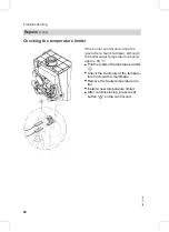
Страница 80: ...ter temperature is below approx 90 C Pull the leads off temperature limiter A Check the continuity of the tempera ture limiter with a multimeter Remove the faulty temperature lim iter Install a new temperature limiter After commissioning press reset button E on the control unit Repairs cont 80 Troubleshooting 5692 536 GB ...

Страница 81: ... with intermediate piece C by pulling it upwards 5 Unscrew air vent valve B from intermediate piece C 6 Fit new air vent valve B onto inter mediate piece C 7 Push air vent valve B with inter mediate piece C into the heat exchanger 8 Push on retaining spring A Check with a hand mirror for correct seat ing 9 Assemble the boiler in reverse order and fill from the primary side Repairs cont 81 Troubles...

Страница 82: ...Checking the fuse 1 Switch OFF the power 2 Release the lateral closures and pivot the control unit down 3 Remove cover A 4 Check fuse F1 Repairs cont 82 Troubleshooting 5692 536 GB ...

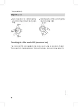
Страница 83: ...w sense a higher temperature If the temperature falls either the motor is turning in the wrong direc tion or the mixer set is incorrectly fitted Mixer installation instruc tions Changing the rotational direction of the mixer motor if required 1 Danger An electric shock can be life threatening Before opening the equip ment switch OFF the ON OFF switch and remove the mains voltage for example by mea...

Страница 84: ...sition II for central heating return from the right Checking the Vitotronic 050 accessories The Vitotronic 050 is connected to the control unit via the LON system To test the connection implement a user check at the boiler control unit see page 31 Repairs cont 84 Troubleshooting 5692 536 GB ...

Страница 85: ...ontrol thermostat to 74 C by the electronic temperature controller to 82 C The temperature limiter in the safety chain locks out the burner con trol unit at a boiler water temperature of 100 C DHW heating DHW heating will be enabled if the cylinder temperature drops 2 5 K below the set cylinder temperature The burner and the cylinder primary pump are switched ON In the deliv ered condition the set...

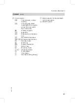
Страница 86: ...is period must lie outside the switching times for standard DHW heating to enable the control unit to recognise the sig nal The set temperature value for backup heating is adjustable in coding address 58 A Pressure gauge B Fault display red C ON indicator green D Reset button Control cont 86 Function description 5692 536 GB ...

Страница 87: ...ate time E Reduced room tempera ture F Set DHW temperature O F Emissions test function K Standby mode L DHW only G Heating and DHW M Party mode N Economy mode b a Adjusting values d Confirmation c Information e Standard setting Reset F Rotary selector for the standard room temperature G ON OFF switch Control cont 87 Function description 5692 536 GB ...

Страница 88: ... The internal extension is integrated into the control unit casing The fol lowing functions are connected to the relay outputs sÖ Internal circulation pump aXA Oil preheater Control cont 88 Function description 5692 536 GB ...

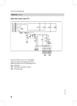
Страница 89: ...mixer sA Cylinder primary pump sK DHW circulation pump fÖ Power supply gÖ Fault notification aVD External blocking terminals 2 3 External demand terminals 1 2 External operating mode chan geover terminal 1 2 The allocation of the External operating mode changeover function is selected via coding address 91 aVF External set value 0 10 V aVG KM BUS Extensions for external connections accessories 89 ...

Страница 90: ...a the exten sion sK DHW circulation pump fÖ Power supply aVD External blocking terminals 2 3 External demand terminals 1 2 External operating mode chan geover terminal 1 2 The allocation of the External operating mode changeover function is selected via coding address 91 aVG KM BUS Extensions for external connections cont 90 Function description 5692 536 GB ...

Страница 91: ...er should be made for each heating circuit Coding The op mode changeover affects d5 0 Changeover in the direction of Constantly reduced or Constantly standby mode respectively in accordance with the se lected set value d5 1 Changeover towards Constantly heating mode The duration of the operating mode changeover can be adjusted in coding address F2 Coding The op mode changeover affects F2 0 No oper...

Страница 92: ...N and OFF for 30 s respec tively over a period of 20 min For a certain period the changeover valve is alternately set towards heat ing mode and DHW heating The burner is switched OFF during the venting program The venting program is activated via coding address 2F 1 The program is automatically disabled after 20 minutes and the coding address is set to 0 Filling program In the delivered condition ...

Страница 93: ...g address 2F The program is automatically disabled after 20 minutes and the coding address is set to 0 Screed drying function The screed function enables screeds to be dried For this always observe the details specified by the screed manufacturer You can select various temperature profiles Temperature profile Diagram 1 DIN 4725 part 4 code F1 1 Temperature profile Diagram 2 ZV parquet and flooring...

Страница 94: ...ofile Diagram 3 code F1 3 Temperature profile Diagram 4 code F1 4 Temperature profile Diagram 5 code F1 5 Temperature profile Factory set code F1 6 to F1 15 Control functions cont 94 Function description 5692 536 GB ...

Страница 95: ... selected heating curve up to the set standard room tempera ture The outside temperature limits for the start and end of the temperature rais ing can be adjusted via the coding addresses F8 and F9 Example of the settings in the delivered condition A Heating curve for operation with standard room temperature B Heating curve for operation with reduced room temperature Control functions cont 95 Funct...

Страница 96: ...rease of the set boiler water temperature or flow temperature can be adjusted in the coding addresses FA and Fb Example for the settings in the delivered condition A Start with standard room tempera ture B Set boiler water or flow tempera ture in accordance with the selected heating curve C Set boiler water or flow tempera ture in accordance with coding address FA 50 C 20 60 C D Duration of operat...

Страница 97: ... of the casing Remote control affects DIP switch set ting Heating circuit without mixer A1 Heating circuit with mixer M2 When connecting a separate room temperature sensor set DIP switch 3 to ON Remote control DIP switch 97 Function description 5692 536 GB ...

Страница 98: ...or aG Flue gas temperature sensor dÖ Stepper motor for diverter valve fJ Temperature limiter gF Ignition unit a Ö Fan a ÖA Fan control aCA Air pressure switch Connection and wiring diagrams internal connections 98 Designs 5692 536 GB ...

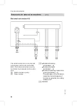
Страница 99: ...A1 Main PCB A2 Power supply unit Connection and wiring diagrams external connections 99 Designs 5692 536 GB ...

Страница 100: ...low loss header Cylinder temperature sensor sÖ Internal circulation pump fÖ Power supply aXA Oil preheater aXF Flame monitor aVG KM BUS aBH Power supply of accessories s A Internal connecting cable Connection diagram plug 201 dF Jumper or fire protection switch a Ö Fan motor s A Internal connecting cable on the main PCB A Oil pump B Fuel valve 1 C Fuel valve 2 Connection and wiring diagrams extern...

Страница 101: ...ead screw M4 x 10 31f Serrated washer A 4 3 31g Cheese head screw M4 x 20 31h Washer A 4 3 31i Cheese head screw M5 x 12 31j Cheese head screw M5 x 8 31k Pan head screw M 4 x 28 31l Cheese head screw M5 x 40 31m Pan head screw M3 x 6 31r Gasket A 10x14x1 5 31s Pivoting angle fitting 31t Countersunk screw M4 x 8 032 Mixer facility lid 033 Connecting pipe 034 Air vent valve 035 Siphon 036 Condensate...

Страница 102: ...10 mm 028 Cleaning brush rotary Parts not shown 025 Oil filter insert Siku 026 Filter bowl magnum 027 Filter insert for item 026 046 Special grease 055 Heat conducting paste 057 Set of fixing parts 059 Installation instructions 060 Service instructions 061 Neutralisation maintenance set 062 Active charcoal filter mainte nance set 065 Solenoid valve core 069 Oil filter changeover set 070 Oil filter...

Страница 103: ...Parts lists cont 103 Parts lists 5692 536 GB ...

Страница 104: ...Parts lists cont 104 Parts lists 5692 536 GB ...

Страница 105: ...Parts lists cont 105 Parts lists 5692 536 GB ...

Страница 106: ...Parts lists cont 106 Parts lists 5692 536 GB ...

Страница 107: ...Parts lists cont 107 Parts lists 5692 536 GB ...

Страница 108: ...tage 1 actual vol set vol Stage 2 actual vol set vol or Oxygen content O2 Stage 1 actual vol set vol Stage 2 actual vol set vol Carbon monoxide content CO Stage 1 actual ppm set ppm Stage 2 actual ppm set ppm Stat burner pressure Stage 1 actual mbar operating phase set mbar Stage 2 actual mbar set mbar Commissioning service reports 108 Commissioning service reports 5692 536 GB ...

Страница 109: ...Service Service Service Service Commissioning service reports cont 109 Commissioning service reports 5692 536 GB ...

Страница 110: ...actual vol set vol Stage 2 actual vol set vol or Oxygen content O2 Stage 1 actual vol set vol Stage 2 actual vol set vol Carbon monoxide content CO Stage 1 actual ppm set ppm Stage 2 actual ppm set ppm Stat burner pressure Stage 1 actual mbar operating phase set mbar Stage 2 actual mbar set mbar Commissioning service reports cont 110 Commissioning service reports 5692 536 GB ...

Страница 111: ...Service Service Service Service Commissioning service reports cont 111 Commissioning service reports 5692 536 GB ...

Страница 112: ...actual vol set vol Stage 2 actual vol set vol or Oxygen content O2 Stage 1 actual vol set vol Stage 2 actual vol set vol Carbon monoxide content CO Stage 1 actual ppm set ppm Stage 2 actual ppm set ppm Stat burner pressure Stage 1 actual mbar operating phase set mbar Stage 2 actual mbar set mbar Commissioning service reports cont 112 Commissioning service reports 5692 536 GB ...

Страница 113: ...Service Service Service Service Commissioning service reports cont 113 Commissioning service reports 5692 536 GB ...

Страница 114: ...tput kW 12 9 19 3 16 1 23 5 Burner stage Stage 1 Stage 2 Stage 1 Stage 2 Rated output at burner stage kW 12 9 19 3 16 1 23 5 Power consumption with circulation pump W 205 255 218 280 Motor speed Oil pump drive r p m 2880 2880 Capacity Oil pump l h 45 45 Burner version Two stage Two stage Product ID _ 0645 BM 112 2 Product characteristics to EnEV Germany Rated output range kW 12 9 19 3 16 1 23 5 Ef...

Страница 115: ...N 60 335 EN 61 000 3 2 EN 61 000 3 3 prEN 13 203 draft Sept 2000 This product complies with the requirements of the Efficiency Directive 92 42 EEC for Low temperature LT boilers The product characteristics determined as system values for the product Vitoplus 300 as part of EC type testing according to the Efficiency Direc tive see specification table can be utilised to assess the energy consumptio...

Страница 116: ...product meets the NOx limits specified by the 1st BImSchV paragraph 7 2 Germany Oil fired condensing boiler Vitoplus 300 Allendorf 11 10 04 Viessmann Werke GmbH Co KG pp Manfred Sommer Manufacturer s certificate according to the 1st BImSchV Germany 116 Certificates 5692 536 GB ...

Страница 117: ... 60 E Extension kit for heating circuit with mixer 83 Extension external 89 90 internal 88 External blocking 92 External demand 92 F Fault code Table 68 Fault display layout 67 Fault history 68 Fault memory 68 Faults 67 Filling function 92 Filling the system 7 Flue gas temperature sensor 79 Flue gas test port 12 Fuse 82 H Heating curve level 34 Heating curve slope 34 Heating curve Adjusting 32 Lev...

Страница 118: ... sensors 64 Screed drying 93 Screed drying function 93 Service level overview 61 Setting the date 9 Setting the time 9 Setting up LON user numbers 30 Siphon Cleaning 23 Filling 9 Specification 114 Standard burner settings 11 Static burner pressure 14 System designs 24 39 System pressure 7 T Temperature limiter 80 Temperature scans 61 Testing functions 64 Testing outputs 64 Testing the flame monito...

Страница 119: ...119 5692 536 GB ...

Страница 120: ...Printed on environmentally friendly chlorine free bleached paper 5692 536 GB Subject to technical modifications Viessmann Werke GmbH Co KG D 35107 Allendorf Telefon 49 6452 70 0 Telefax 49 6452 70 2780 www viessmann com Viessmann Limited Hortonwood 30 Telford Shropshire TF1 7YP GB Telephone 44 1952 675000 Fax 44 1952 675040 E mail info uk viessmann com ...

Отзывы: