


Vertiv
|
NetSure™ 2100 Series -48 VDC Power System Installation Manual (IM582138000)
|
Rev. C
58
Table 3:
Mini Control Unit RJ-45 Ethernet Port Pin Configuration
Port Pin Number
Name
Definition
1
Tx+
Write
2
Tx-
Write Signal -
3
Rx+
Read
4
--
no connection
5
--
no connection
6
Rx-
Read Signal -
7
--
no connection
8
--
no connection
Mini Control Unit Second Ethernet Port Connection (if Optional External IB4 Kit P/N
559239 Furnished)
General
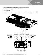
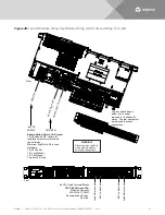
Your system may be connected to an external IB4 assembly (see “Installing an Optional External IB4 Kit P/N
559239” on page 38). The IB4 assembly provides a second Ethernet port. When the system is connected to an
external IB4 assembly, the Ethernet port located on the Mini Control Unit’s front panel can ONLY be used to
connect a computer directly to the Mini Control Unit and the Ethernet port located on the IB4 assembly is to be
used to connect the Mini Control Unit to your Local Area Network (LAN).
NOTE!
If your system is connected to an IB4 assembly, DO NOT connect your Local Area Network
(LAN) to the Mini Control Unit’s front panel Ethernet port.
Default IB4 Ethernet Port Parameters
IPv4
IP Address:
192.168.1.2
Subnet Mask:
255.255.255.0
Default Gateway: 192.168.1.1
IPv6
IPv6 Address:
20fa:fffd:fffc:fffb:fffa:fff9:fff8:fff7
IPv6 Prefix:
0
IPv6 Gateway:
20fa:1:fffe:ffff:fffe:fffd:ffff:fffe
Procedure
1.
An RJ-45 10BaseT jack is provided on the IB4 assembly for connection into a customer's network. This
jack has a standard Ethernet pin configuration scheme, twisted pair. Refer to
for pin outs. Use shielded Ethernet cable (grounded at both ends). Note that the IB4 board’s
RJ-45 jack is connected to chassis ground. Refer to the Mini Control Unit Instructions (UM1M831ANA)
for operational details.


