


Vertiv
|
NetSure™ 2100 Series -48 VDC Power System Installation Manual (IM582138000)
|
Rev. C
50
Table 2:
Programmable Digital Inputs
Programmable
Digital Input
J3 Pin No.
Cable P/N 565286
Color Scheme
Dedicated to...
1
J3-1
+
W-BL
User Defined
J3-3
–
W-O
2
J3-2
+
BL-W
User Defined
J3-4
–
O-W
Programmable
Relay Output
J3 Pin No.
Cable P/N 565286
Color Scheme
Alarms Assigned to
this Relay (Default)
1
(Note 1)
J3-10
NO
S-W
User Defined
J3-8
COM
BR-W
J3-6
NC
G-W
2
J3-9
NO
W-S
User Defined
J3-7
COM
W-BR
J3-5
NC
W-G
3
J3-16
NO
G-R
User Defined
J3-14
COM
O-R
J3-12
NC
BL-R
4
J3-15
NO
R-G
User Defined
J3-13
COM
R-O
J3-11
NC
R-BL
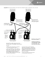
CAUTION!
All conductors in this harness may be connected within the cabinet. Shorting or grounding
of unused conductors may result in service interruption or equipment damage. Therefore insulate all
conductor ends not being used in your application.
NOTE 1:
The controller relay assigned to “Critical Summary” alarm (relay 1 by default) will operate in the
“Fail Safe Mode”. “Fail Safe Mode” means Relay 1 is de-energized during an alarm condition, opening the
contacts between the C and NO terminals, and closing the contacts between the C and NC terminals.
The controller’s three (3) remaining relays energize during an alarm condition, closing the contacts
between the C and NO terminals, and opening the contacts between the C and NC terminals.


