


Vertiv
|
NetSure™ 2100 Series -48 VDC Power System Installation Manual (IM582138000)
|
Rev. C
49
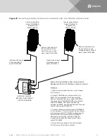
CAUTION!
All conductors in this cable may be connected within the shelf. Shorting or grounding of
unused conductors may result in service interruption or equipment damage. Therefore, insulate all
conductor ends not being used in your application.
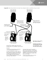
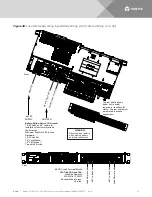
Digital Inputs
You can connect up to two (2) digital inputs to the system. Note that you must supply both paths for the digital
input (either a positive or a negative signal and the opposite polarity return path). Observe proper polarity.
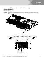
Refer to
for terminal locations and
The digital inputs can be programmed to provide an alarm when the signal is applied (HIGH) or removed
(LOW). Refer to the Mini Control Unit Instructions (UM1M831ANA) for programming information.
Digital Input Ratings: Refer to the following.
a)
Maximum Voltage Rating: 60V DC.
b)
Active High: > 19V DC.
c)
Active Low: < 1V DC.
The digital inputs may be preprogrammed for specific functions. Refer to the configuration drawing
(C-drawing) supplied with your system for your system’s specific configuration.
Procedure
1.
Connect up to two (2) digital inputs to the system. Refer to
for terminal locations and
for pin-out information.
Programmable Relay Outputs
The system has four (4) programmable alarm relays with dry Form-C contacts. Refer to
locations and
Refer to the Mini Control Unit Instructions (UM1M831ANA) for programming information.
Relay Ratings: Refer to the following.
a)
Steady State: 0.5 A @ 60 VDC, 1 A @ 30 VDC.
b)
Peak: 3 A @ 30 VDC.
The relays may be preprogrammed for specific functions. Refer to the configuration drawing (C-drawing)
supplied with your system for your system’s specific configuration.
Procedure
1.
Connect up to four (4) relay outputs to the system. Refer to
for terminal locations and


