


Vertiv
|
NetSure™ 2100 Series -48 VDC Power System Installation Manual (IM582138000)
|
Rev. C
55
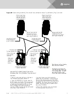
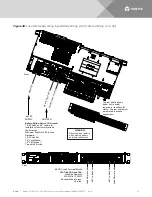
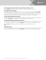
Figure 31:
Alarm Wiring to Battery Disconnect Circuit Breaker when One (1) Battery Cabinet is Used
Alarm Wiring to Battery Disconnect Circuit
Breaker when One (1) Battery Cabinet is Used
Procedure
1. Remove resistor faston tab from circuit breaker
“NC” terminal.
2. Connect ORANGE wire of alarm cable P/N
565513 to circuit breaker “NC” alarm terminal.
Remove faston tab from alarm cable P/N 565513
and splice end to ORANGE/WHITE wire of alarm
cable P/N 565286. Note splice and sleeving
included in 565286. Insulate and tie back all unused
wires of alarm cable P/N 565513.
3. Connect Yellow wire of alarm cable P/N 545696
to circuit breaker “C” alarm terminal. Remove faston
tab from alarm cable P/N 545696 and splice end to
BLUE/WHITE wire of alarm cable P/N 565286.
Note splice and sleeving included in 565286.
Insulate and tie back all unused wires of alarm
cable P/N 545696.
4. There is NO connection to the circuit breaker
“NO (Normally Open)” alarm terminal.
Yellow Jumper/Alarm
Cable (P/N 545696)
(Supplied with
battery cabinet.)
Remove faston tab first,
then splice wire to the
blue/white wire of shelf
alarm cable P/N 565286.
Remove faston tab first,
then splice wire to the
orange/white wire of shelf
alarm cable P/N 565286.
Insulate and tie back
all unused wires of
cable P/N 545696.
Orange Jumper/Alarm
Cable (P/N 565513)
(Supplied with
battery cabinet.)
Insulate and tie back
all unused wires of
cable P/N 565513.
BATTERY CABINET
BATTERY DISCONNECT
CIRCUIT BREAKER


