


Vertiv
|
NetSure™ 2100 Series -48 VDC Power System Installation Manual (IM582138000)
|
Rev. C
41
System Shelf Frame Grounding Connection
For shelf grounding requirements, refer to the current edition of the American National Standards Institute
(ANSI) approved National Fire Protection Association's (NFPA) National Electrical Code (NEC), applicable local
codes, and your specific site requirements.
NOTE!
The DC return connection to this system can remain isolated from system frame and chassis
(DC-I).
NOTE!
This system is suitable for installation as part of the Common Bonding Network (CBN).
Relay or Cabinet Rack
Procedure
1.
The frame grounding connection to the shelf is made by using grounding washers with the mounting
hardware used to secure the shelf to the relay rack or cabinet. Refer to “Securing the System to a Relay
Rack or a Cabinet Equipment Rack (if required)” on page 18. Ensure that the relay rack or cabinet is
properly grounded.
NOTE!
An
M4 frame ground stud is located on the rear of the system shelf. Provide a grounding lead to
this stud, if required. Refer to
Wall Mounting
Procedure
1.
An M4 frame ground stud is located on the rear of the system shelf. Refer to
Provide a grounding lead to this stud as required.
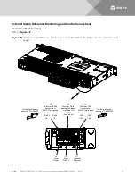
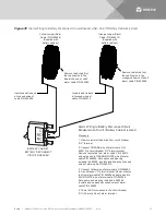
Figure 25:
System Shelf Frame Grounding Connection Point
Central Office Ground Connection
Landing points are provided on the battery return bus for a central office ground lead (see
on page 63,
on page 68). For central office grounding
requirements, refer to the current edition of the American National Standards Institute (ANSI) approved
National Fire Protection Association's (NFPA) National Electrical Code (NEC), applicable local codes, and your
specific site requirements.
M4 Shelf Frame Ground Stud


