User Manual 10H52258UM60 - Rev. 3 - 01/2019
78
APM 400/600
Optional Components
Dimensions (H × W × D) (mm)
Inductor value (uH)
305 × 190 × 145
7±10%
Each UPS cabinet is fitted with three bypass load sharing inductors, without occupying any extra clearance. The
load sharing rate is generally 10% of the system rated current with the difference of external cable configuration.
If possible, the length of the cables between the bypass and each UPS, and from the UPS module output to the
parallel system connection point should be the same.
Preparation
1. Prepare the installation tools, including an electric screwdriver, a screw driver, a torque sleeve and a red
marker.
2. Check that all installation materials, types and cables are present and complete, and that the auxiliary materials
(such as fastener, heat shrinkable tube and wire clasp) are present and in good condition.
Procedures
Warning
1. Only authorized personnel may install and replace the inductors.
2. Connect the cables adhering strictly to the instructions. Failure to do so may result in damage to the UPS
and the inductors.
1. Set all the power switches, e.g. battery and load, to the OFF position.
2. All the LCDS are off, wait five minutes for the UPS internal DC bus capacitors to discharge completely.
3. Remove all the screws connecting the 400 kVA power cabinet and power distribution cabinets together. Then
remove the 400 kVA power cabinet and its rear panel. Keep the screws in a safe place.
4. Extract the bypass control module and bypass power module.
5. Disconnect the cables W01, W02 and W03 from the bypass power module input terminals.
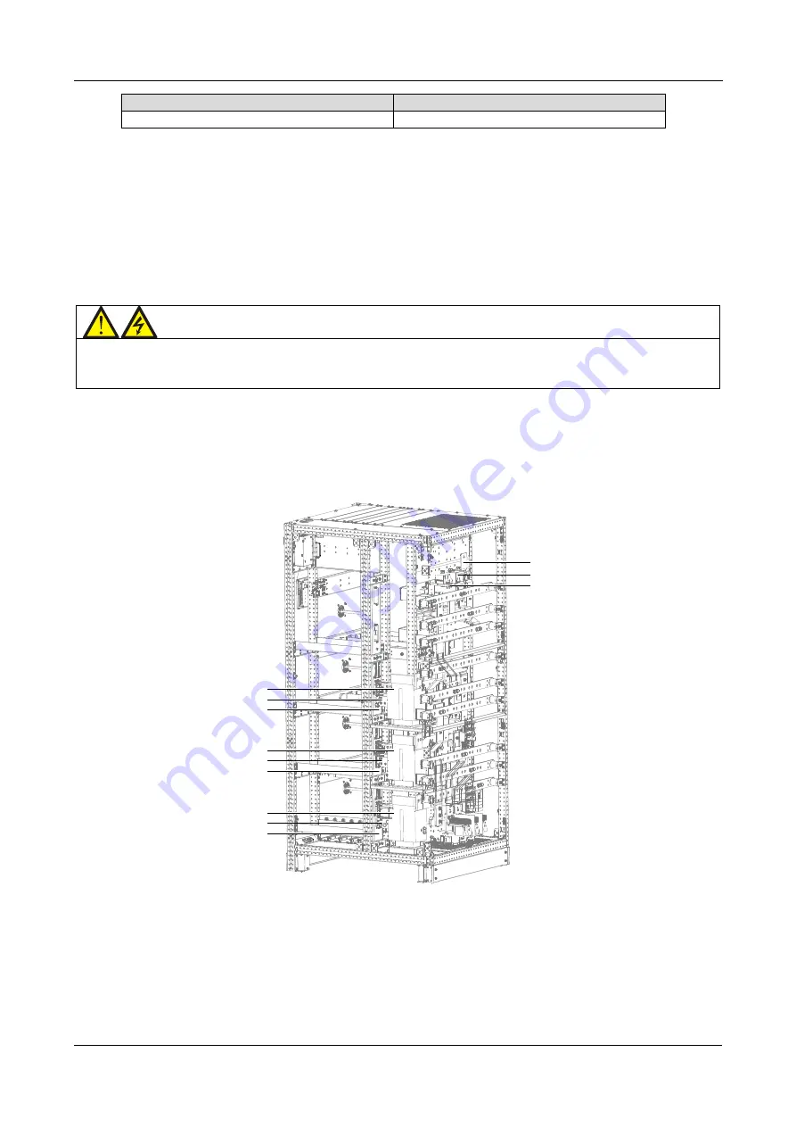
oA
oB
oC
LA
LA-2
LA-1
LB
LB-2
LB-1
LC
LC-2
LC-1
Figure
9-1 -
Installing the bypass load sharing inductors
6. Place the three inductors in the installation positions LA, LB and LC, and use three M12 x 30 hexagon head
screws to connect the power cables between LA-1, LB-1, LC-1 and one end of the bA/L1-B (A), bA/L1-B (B),
bA/L1-B (C), as shown in Figure 9-1.
7. Use the six M12 x 30 hexagon screws screw and the cables w07 (bA), W08 (bB), W09 (bC) to connect the
terminals of LA-2, LB-2, LC-2 to the bypass power module, as shown in Figure 9-1.
8. Leave the connection cables between the bypass power module output terminal and terminals (oA, oB, oC) as
they are.
Содержание Liebert APM 400
Страница 1: ...Liebert APM 400 600kW User Manual ...
Страница 2: ...APM 400 600 UNINTERRUPTIBLE POWER SUPPLY USER MANUAL 10H52258UM60 rev 3 ...
Страница 3: ......


