User Manual 10H52258UM60 - Rev. 3 - 01/2019
62
APM 400/600
Battery
7
Battery
This chapter deals with the various aspects of the UPS battery, safety precautions, battery management, battery
functions, and BCB box connections, as well as the battery disposal procedure.
7.1
Overview
The UPS battery string consists of a number of batteries connected in a series. It provides an appropriately rated
DC input voltage for the UPS inverter. The required battery backup time (i.e. the time that the battery is able to
supply the load for following a mains failure) depends on the ampere-hour rating of the battery. Under certain
conditions it may be necessary to connect several battery strings in parallel. In order to facilitate the UPS
installation, the battery is usually installed on a specific designed battery rack or in a battery room.
During maintenance or repair operations, the battery must be disconnected from the UPS. This achieved by
means of a suitably rated battery circuit breaker. This circuit breaker shall be located as close as possible to the
battery connecting terminal. The length of the power and signal cables connected to the UPS must be kept to a
minimum.
It may be necessary to connect several battery strings to the UPS in parallel in order to increase the battery
back-up time. Each string must be fitted with its own disconnecting device so that it is possible to carry out
maintenance work on any given string, without affecting the normal operation of other battery strings.
7.2
Safety Precautions
This section covers the various precautions and safety measures that should be observed when working with and
handling UPS batteries. Users must adhere strictly to the measures included in this section in order to avoid
severe injury or damage to the equipment.
Warning
•
When all the blocks are connected together, the battery string voltage may be very high (up to 540 Vdc).
This can be lethal and may result in severe injury. Only qualified personnel are permitted to install, operate, and
service the battery.
•
Install all the batteries inside a lockable cabinet or in a specifically-designed battery room so that they can
be accessed only by the qualified service personnel. Confirm the battery switch has been disconnected prior to
servicing batteries.
•
No user-serviceable components are located behind the covers that require the use of a tool for removal.
The voltage behind the covers is hazardous and potential lethal.
•
Before working on the copper bars connected to the external batteries, ensure that they are disconnected
from all the power supplies.
•
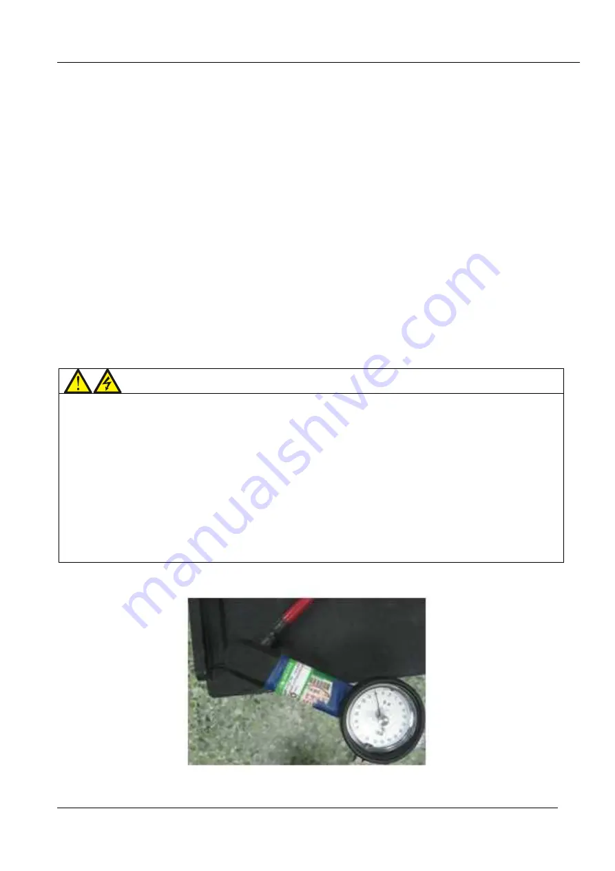
Tighten the battery terminal bolts by applying the specified torque. Avoid applying too much or too small
torque as this may result in poor electrical connections; under certain conditions this may result in arcing or heat
accumulation, which may cause fires.
Figure 7-1 and 7-2 illustrate the correct and incorrect connection methods respectively:
Figure 7-1 Correct connection method
Содержание Liebert APM 400
Страница 1: ...Liebert APM 400 600kW User Manual ...
Страница 2: ...APM 400 600 UNINTERRUPTIBLE POWER SUPPLY USER MANUAL 10H52258UM60 rev 3 ...
Страница 3: ......


