


49
User Manual 10H52258UM60 - Rev. 3 - 01/2019
Introducing UPS Operations
APM 400/600
the specifications of the system protection device.
If either of the two situations arises, the corresponding alarm messages will appear on the UPS operator control
and display panel.
(Parallel System)
The control logic system constantly monitors load requirements and controls the power
supplied by the two UPS modules. In the event that an overload condition is sustained for greater than a preset
time, the load will transfer to the bypass, when the number of active modules is unable to satisfy load
requirements. The load returns to the inverter if the power is reduced to a value that can be sustained by the
number of active modules in the system.
Maintenance bypass
The UPS is equipped with a maintenance bypass that provides a safe working environment for the engineers
when carrying out ordinary maintenance or repairs on the UPS system, while simultaneously providing
unregulated mains supply to the loads. The maintenance bypass can be manually selected by turning the
maintenance bypass switch to the ON position, and disconnected by turning it to the OFF position.
UPS Power Supply Switch Configuration
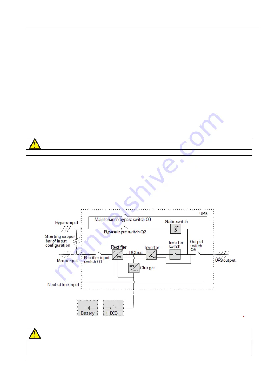
The UPS is equipped with four switches: the rectifier input switch Q1, bypass input switch Q2, maintenance
bypass switch Q3, and output switch Q5.
Note
Switches Q1, Q2, and Q5 are optional, whereas switch Q3 is fitted on the standard configuration.
Figure 6-2 illustrates the block diagram of the UPS module. The UPS may be used in split bypass (where the
bypass is supplied by an independent main input) or common input configuration. In the split bypass
configuration, the static bypass and maintenance bypass share the same independent bypass power supply. If a
separate power source is not available, the input supply connections of the bypass input switch (Q2) and rectifier
input switch (Q1) must be linked together (the UPS is delivered in the split bypass configuration) so that the
bypass input and rectifier input use the mains input power source.
During normal UPS operation, all switches, with the exception of the maintenance bypass switch Q3, should be
closed.
Figure 6-2 UPS power supply switch configuration
Note
The mains input and bypass input share the same neutral line.
The user can activate maintenance mode by closing the external maintenance bypass switch on the individual
module .
Содержание Liebert APM 400
Страница 1: ...Liebert APM 400 600kW User Manual ...
Страница 2: ...APM 400 600 UNINTERRUPTIBLE POWER SUPPLY USER MANUAL 10H52258UM60 rev 3 ...
Страница 3: ......