22-1
22
3-Wire C.L. Sensor Setup
The 3-Wire C.L. (Current Loop) (Type B) Sensor Setup function allows you to enter information about dispenser
pan and containment sump sensors installed at the site. You must enter data individually for each sensor. The
information you enter tells the system the number and location of installed sensors.
Selecting the 3-Wire C.L. Sensor Setup Function
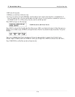
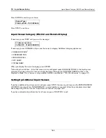
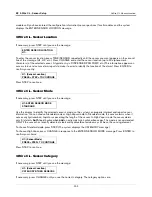
To select 3-Wire C.L. Sensor Setup, press FUNCTION until you see the message:
Press STEP to continue.
3-Wire C.L. Sensor Configuration
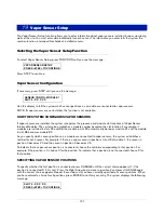
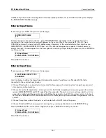
If necessary, press STEP until you see the message:
Use this display to tell the system which sensor positions on a module are connected to 3-Wire C.L. sensors.
NOTE: If dispenser pan and containment sump sensors are not installed, this function is not available.
HOW THE SYSTEM CONFIGURES 3-WIRE C.L. SENSORS
If dispenser pan and containment sump sensors are installed, the system will recognize the presence and module
slot locations of Type B Interface Modules. The system also establishes a module number based on the slot
location. For example, if modules are installed in slots #3 and #6, the module in slot #3 automatically becomes
module #1 and the module in slot #6 becomes module #2.
As you specify which positions on a module are connected to 3-Wire C.L. sensors, the system establishes a
number for each sensor. For example, if there is a sensor in positions 3 and 5 of module 1, the sensor in position 3
becomes H3 and the sensor in position 5 becomes H5.
To indicate that a sensor position is connected, choose the number corresponding to that position. For example, if
the position is 3, choose 3 for the position. To indicate that a position is not connected, choose X for that position.
SPECIFYING 3-WIRE C.L. SENSOR POSITIONS
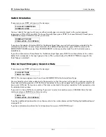
To indicate whether position 1 is connected, press CHANGE until the correct choice appears (1 if the position is
connected, X if it is not). Press the Right Arrow key to move to position 2 and press CHANGE again until the
correct choice appears. Repeat these steps until you have correctly specified all sensor positions. When you have
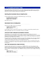
entered a choice for all positions, press ENTER to confirm your entry. The system displays the following message:
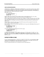
Press STEP. If more than one module is installed, the system automatically advances to the SENSOR CONFIG
message for the next module. Up to 8 modules may be installed. Repeat the steps described above for each
3 WIRE C.L. SENSOR SETUP
PRESS <STEP> TO CONTINUE
SENSOR CONFIG - MODULE 1
SLOT # - X X X X X
SLOT # - X X X X X
PRESS <STEP> TO CONTINUE


