Models 947, 948 and 960 Leak Detectors Operations and Service Manual
2-5
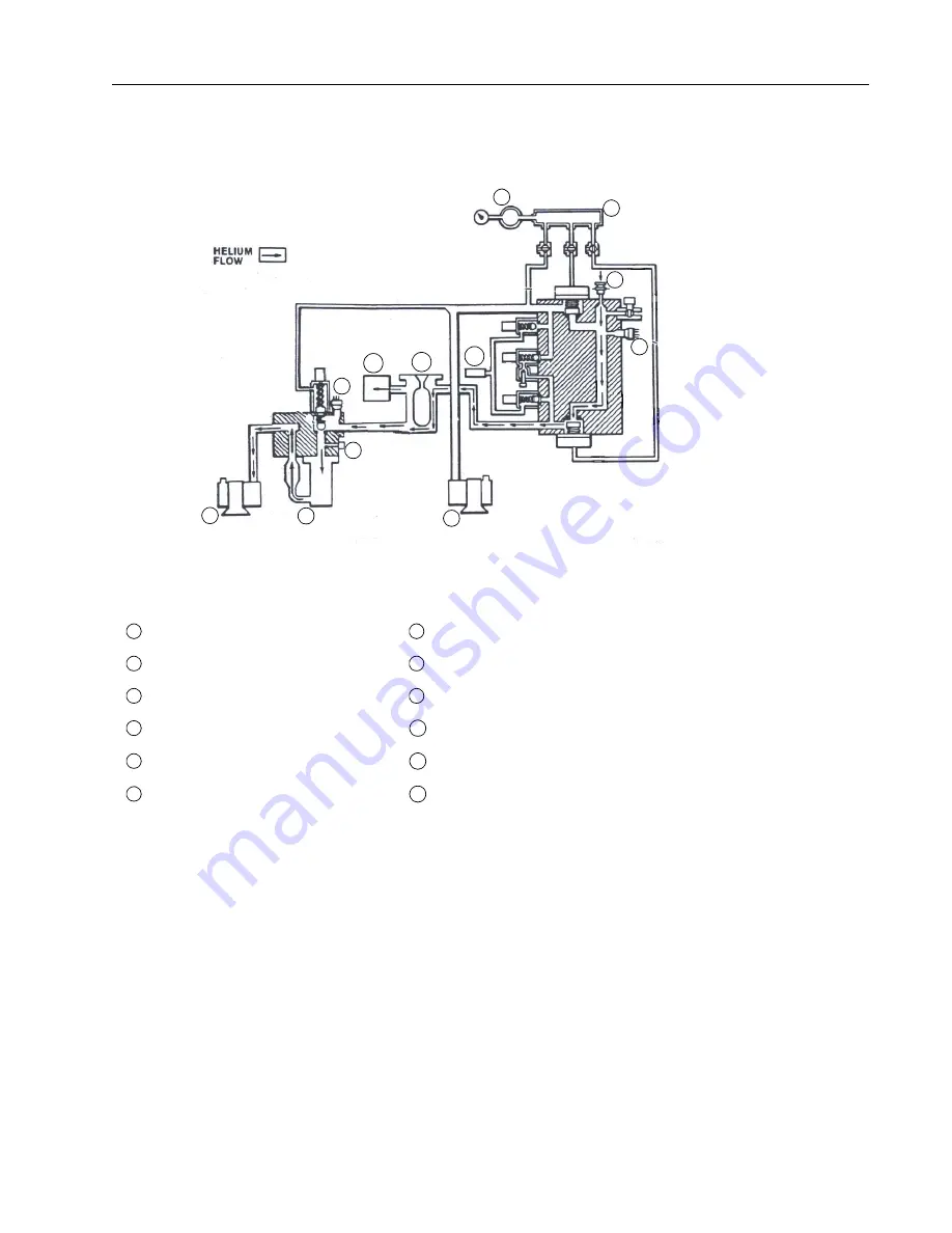
In Figure 2-3, numbers in white circles designate the location of valves. Other key parts of
the vacuum system, represented by numbers in black circles, are identified after Figure 2-3.
Figure 2-3
960 Flow Diagram
Reservoir
Thermocouple Gauge (TC1)
❶
Rough Valve
Turbo/Diffusion Pump
Thermocouple (TC2)
❷
Test Valve
Forepump
System Pressure Gauge
❸
Vent Valve
Rough Pump
Standard Leak
❹
Gross Leak Valve
Manifold
Nitrogen Cold Trap
Test Port
Spec Tube
1
2
4
5
6
7
8
9
3
10
11
12
❶
❷
❸
❹
1
7
2
8
3
9
4
10
5
11
6
12
Содержание 948
Страница 8: ...Models 947 948 and 960 Leak Detectors Operations and Service Manual This page intentionally left blank...
Страница 12: ...Models 947 948 and 960 Leak Detectors Operations and Service Manual This page intentionally left blank...
Страница 36: ...Models 947 948 and 960 Leak Detectors Operations and Service Manual This page intentionally left blank...
Страница 102: ...Models 947 948 and 960 Leak Detectors Operations and Service Manual This page intentionally left blank...
Страница 144: ...Models 947 948 and 960 Leak Detectors Operations and Service Manual This page intentionally left blank...
Страница 152: ...Models 947 948 and 960 Leak Detectors Operations and Service Manual This page intentionally left blank...
Страница 162: ...Models 947 948 and 960 Leak Detectors Operations and Service Manual This page intentionally left blank...
Страница 175: ......


