background image

UVITEC – Cambridge                                                                                                                                                                          
90/225 


Some images has a 12, 14 or 16-bit format and Windows® 
can only display 8-bit images (256 grey levels).  
 
Due to this limitation, the FireReader 1D software handles 
two images: 
A “memory” image corresponding to the 12, 14 or 16-bit 
format (4 096, 16 384 or 65 536 grey levels) 
A “display image” corresponding to the image displayed on 
the screen (256 grey levels) 
 
The easiest way to calculate the “display image” would be 
to translate the full grey scale each time an image is 
acquired: the x grey levels values of the “memory” image 
corresponds to 256 values in the displayed image. In that 
case, it won’t be possible to visualise faint spots on a dark 
image. 
 
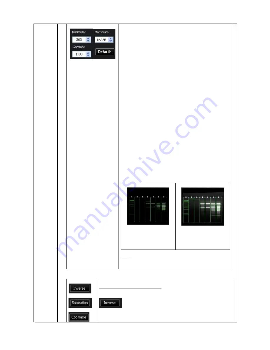
FireReader 1D offers the possibility to select the grey level 
range to translate for the display image calculation. All the 
grey levels under the “Min value” defined will be converted 
to 0 (Black) in the displayed image. All the grey levels 
upper the “Max Value” defined will be set to 255 (White) in 
the displayed image. The grey levels between those two 
limits will be converted in an intermediate grey level value 
following a linear rule. 
 
For both values, you can: 

  Edit the value in the corresponding field 

  Select the value by dragging and dropping the arrow 

  Click on the “optimum display” button: FireReader 1D 

will then calculate the ideal values to be selected 
according to the parameters defined 


Default optimum display 


Optimum display 

enhancement 

The image appears 

brighter. The faint bands 

are more visible. 

 
Note: The optimum display has no impact on the 
analysis. Only the display of the image is modified. 


Inverse or display pseudo color 


 Click on the “Inverse” icon to inverse the grey level of the 

image. This makes a negative image 
 

Содержание FIREREADER MAX

Страница 1: ...UVITEC Cambridge 1 225 F F F FIRE IRE IRE IRER R R READER EADER EADER EADER MAX MAX MAX MAX U S E R S E R V I C E M A N U A L 07 2012 index j ...

Страница 2: ...ra to the computer before installing the FireReader 1D software After the software is fully installed connect the FireReader USB camera to the computer At that time Windows 7 Vista or XP will look for the camera driver located in the CD Rom Complete installation procedure are described in this manual Please refer to the complete details before to proceeding to the installation ...

Страница 3: ...0 ou un masque de protection Réf MP 80 ou MP 800 CONSERVER SOIGNEUSEMENT CES INSTRUCTIONS AVVERTIMENTO Durante l utilizzo di questo apparecchio il non rispetto delle istruzioni puo provocare bruciature gravi all utilizzatore ATTENZIONE I raggi Ultra Violetti essendo pericolosi per gli occhi e la pelle esposti senza protezione è obbligatorio portare gli occhiali Ref LP 70 oppure una maschera di pro...

Страница 4: ...d to answer any question you may have We are also very receptive to your suggestions Many of the new features and enhancements in this system are a direct result of conversations with our customers Please do not hesitate to contact us to let us know what you would like to see in the next version of this system You can contact us at the following addresses Email uvi uvitec co uk Contact address UVI...

Страница 5: ...19 Pre requirement 19 Software installation Preliminary steps 19 Windows XP and Vista warning 20 Software installation 20 Connecting the camera 26 Connecting the darkroom Auto motorized zoom series only 27 Upgrading the software 29 FireReader 1D un install 29 Video card related problems Windows XP Vista 29 Darkroom control board driver installation 30 Trouble shooting Windows device manager 32 USI...

Страница 6: ...ection 94 Return to the 1D acquisition module 95 M A N U A L C O U N T I N G 96 Manual counting 96 Return to the 1D acquisition module 97 DISTANCE CALCULATION MODULE 98 Objectives and output 98 Distance calculation module operating environment 99 Toolbar in details 101 1 D E T E C T 108 A Edit lane 108 B Edit band 111 C Distance 114 2 A N A L Y S E D I S T A N C E 117 A Distance results 117 Return...

Страница 7: ...Access to the Lower image bar 191 Image compare 193 Good laboratory practice file 194 Copy 195 Autofit 195 Zoom 196 THE APPLICATION PROTOCOL 197 What is an Application protocol 197 Access to the Application protocol 198 Application protocol in details 200 Exposure Exposure predefined set up 201 Live Live preview pre defined parameters 207 Display Image display pre defined parameters 209 Printing I...

Страница 8: ...UVITEC Cambridge 8 225 General advices 221 Spare parts FireReader series 221 WARRANTY 223 CONFORMITY 225 ...

Страница 9: ... has been developed by our experts especially for your scientific applications This association of our exclusive electronic high quality optics and advanced software delivers outstanding performance With FIREREADER you simply reach the lowest limits of detection on all of your samples THE APPLICATIONS MASTER The FireReader covers most of the molecular biology imaging requirements Fluorescence visi...

Страница 10: ... from UV radiation The use of protective goggles mask and or gloves is strongly recommended This product is safe to use when operated in accordance with the instruction manual This instrument should not be modified or altered in any way Modification or alteration of this instrument will void the manufacturer s warranty void the regulatory certifications and create a potential safety hazard The int...

Страница 11: ...sta Windows 7 Excel Microsoft and Power Point are trademarks of Microsoft Corporation Intel Pentium Intel Core are trademarks of Intel Corporation FireWire Mac and Mac OS X are trademarks of Apple Inc Coomassie is a trademark of BASF Aktiengesellschaft Cy is a trademark of GE Healthcare group companies SYBR Safe SYBR Green SYBR Gold and SYPRO are trademarks of Invitrogen Corporation Other brands o...

Страница 12: ...lete agreement between you and Uvitec Ltd By opening the software package or using the CD you are consenting to be bound by and are becoming a party to this agreement If you do not agree To all of the terms of this agreement do not open the package or use the CD Promptly return the CD including the written materials the binder and all other equipment containers to the dealer from whom you purchase...

Страница 13: ... the original copyright notice and or other legend is reproduced on each copy Terms and Termination This license agreement takes effect upon your use of the software and remains effective until terminated You may terminate it at any time by destroying all copies of the Software and Documentation in your possession It will also automatically terminate if you fail to comply with any term or conditio...

Страница 14: ...deo card 1280x1024 16 millions color mode 24 bit Upper resolutions supported Video card with a refresh rate above 70Hz Operating system Microsoft Windows XP SP3 and upper 32 bit only Microsoft Windows Vista SP2 and upper 32 or 64 bit Microsoft Windows 7 SP1 and upper 32 or 64 bit USB Port At least two USB ports available UVITEC LTD cannot guaranty the correct working of the computer and the softwa...

Страница 15: ...rotective plastic cover Place the darkroom at its permanent location the door facing forward The cabinet has to be placed near the computer used for image acquisition It is recommended that the FIREREADER darkroom be carried by at least two people one on each side holding the instrument from the bottom side Be sure that the door is properly closed when carrying the instrument Do not connect the po...

Страница 16: ...m WARNING The use of the FIREREADER involves ultraviolet UV illumination Proper precautions must be taken to avoid eye and skin exposure to the UV light This instrument is meant for use only by specialised personnel that know the health risks associated with UV radiation and the chemicals that are normally used with this instrument WARNING The operator should wear appropriate safety glasses or a p...

Страница 17: ...sta or XP will look for the camera driver located in the CD Rom 1 Connect all items 1 Install the darkroom by the computer 2 Fix the set Camera Zoom Extra lens on the camera support with the knurled knob Illustration 1 the camera optics on its support The camera optics are already installed on its support This support need to be fixed on the top of the darkroom by the two fixing knob as described ...

Страница 18: ...UVITEC Cambridge 18 225 Illustration 2 the camera optics installed on the top of the darkroom rear side Illustration 3 the camera optics installed on the top of the darkroom front side ...

Страница 19: ...r XP will look for the camera driver located in the CD Rom The FireReader system should be switched off before any software installation Software installation Preliminary steps The CD disk provided with your FireReader system contains the Capt Advance software and driver Capt Advance runs with Microsoft Windows TM XP 32 bit mode Vista 32 bit or 64 bit mode and Windows 7 32 bit or 64 bit mode Windo...

Страница 20: ...s fully completed Step 1 Insert the CD ROM in the CD ROM drive Ensure that all other application programs are closed Windows XP Vista and Windows 7 users should also ensure that they are logged on with administrator privileges If the Autorun option is set on your computer the installation automatically starts If not double click on the Autorun exe file to start the installation of the software Ple...

Страница 21: ...tware icon A pop up window displays the following Windows installation authorization message Click on the Install button The setup wizard will then start to initialize This could take up to 1 minute The setup wizard will then start the installation process ...

Страница 22: ...me screen is displayed click on NEXT to continue Click on NEXT to continue Select the Destination directory c Program files Uvitec Alliance by default Then click on NEXT Program files are installed in the specified directory and group created ...

Страница 23: ...en the software installation is complete click on Finish The system will then start the driver installation process The setup wizard will then install the USB controller driver Click on Install to install the system s USB driver ...

Страница 24: ... pop up window displays the following camera driver installation message Click Next to continue The following messages are then successively displayed A pop up window displays the following security message Windows 7 Select the Install option Windows XP ...

Страница 25: ...r the restart switch on the FireReader system Keep the FireReader 1D CD Rom in the CD Rom drive of your computer The darkroom driver is then installed by Windows FireReader Auto only This driver is related to the FireReader darkroom management Wait for 10 seconds and double click on the FireReader icon The camera driver is then installed by Windows The following message should appears for the Fire...

Страница 26: ...room into an earthed socket Plug the computer and the monitor into an earthed socket 1 Connect the camera USB cable to the computer USB port rear side FIG 1 USB CAMERA CONNECTION Computer rear side Connection Connect the cable coming from the USB camera to the computer USB port Note Always connect to a computer rear side USB port ...

Страница 27: ...ries only 2 Connect the USB cable from the darkroom to the computer USB port Note Always connect to a computer rear side USB port Computer rear side USB cable connection FIG 1 ZOOM CONNECTION X PRESS SERIES ONLY WITH MOTORISED ZOOM LENS 1 ZOOM TO THE DARKROOM Cable from the zoom lens Darkroom rear side ...

Страница 28: ...cable connection Computer rear side USB cable connection It is mandatory to connect the system to an appropriate AC voltage outlet that is properly grounded and protected by a circuit breaker Connecting to ground constitutes an obligatory protection ...

Страница 29: ...der 1D software will do it for you Click on Start button Go to Programs Choose UVITec and click on uninstFireReader 1D Answer Yes to the question and programs are removed Click on Ok to finish de installation Video card related problems Windows XP Vista When the graphics acceleration is set too high on certain video cards the FireReader 1D program could crash when using the Live Image feature or t...

Страница 30: ... independent power supply USB motorized zoom driver filter wheel The motorized zoom USB driver is installed at the same time that the FireReader 1D software No specific installation is required If the FireReader 1D software does not detect the motorized zoom lens we recommend checking first if the zoom is properly connected to the USB port If the problem is not resolved we recommend to re install ...

Страница 31: ...g that this driver has not passed the Windows Logo testing is displayed Even though our driver works on Windows XP it is not numerically signed so click on Continue anyway button to continue the installation Once the driver is installed click on Finish button to validate the driver installation ...

Страница 32: ... of installation issue we recommend to check the driver status using the Windows Device Manager To do so from the Windows start menu select Control Panel The software opens the Windows setting options For Windows 7 select System and security then system then Device Manager ...

Страница 33: ...UVITEC Cambridge 33 225 The Device Manager should appear as below for the FireReader and SL4 USB series ...

Страница 34: ...ion and the chemicals that are normally used with this instrument WARNING The operator should wear appropriate safety glasses or a protective mask and gloves UV radiation can be dangerous for unprotected eyes and skin therefore we recommend the user to wear UV protective goggles LP 70 or face shield MP 80 or MP 800 Caution Switch off the transilluminator when gel is not present on the UV filter If...

Страница 35: ... D56 D59 main switch is located on the darkroom right hand side Darkroom right hand side Switch on the main switch before to use the system Darkroom back side power supply and optional USB motorized zoom lens connection USB board Optional for Auto versions motorized zoom lens POWER switch ...

Страница 36: ...light by putting the switch to the position 0 Transilluminator Case 1 security on when the door is open Switch on the door security switch to the 0 position to activate the UV security when the door is opened Switch on the transilluminator command The door is opened and the UV transilluminator is off Case 2 security off when the door is open Switch off the door security switch to the 1 position to...

Страница 37: ...sition to activate the UV security when the door is opened Switch on the transilluminator command The door is opened and the UV transilluminator is off Case 2 security off when the door is open Switch off the door security switch to the 1 position to inactivate the UV security when the door is opened The security switch s diode will light on Switch on the transilluminator command The door is opene...

Страница 38: ...omide application Install the filter on the hole in front of you The filter number corresponds to the number indicated on the filter wheel for instance number one to 1 to 6 To select a filter hole turn the black handle in way to have the filter indication of your choice in front of you Figure 2 Top of the darkroom To install a filter slightly unscrew the knob and turn the camera holder from the ri...

Страница 39: ...luminator switch is turned ON Mask and gloves are recommended to block the UV radiation WARNING The system should be located away from water solvents or a corrosive material on a bench top that is dry and stable The system should be placed away from interfering electrical signals and magnetic fields A dedicated electrical outlet should be used to eliminate electrical interference from other instru...

Страница 40: ...eatures reference the appropriate part of this manual Power on the computer After the computer has booted up completely switch on the FireReader system Wait for 10 seconds and double click on the FireReader icon The software opens on the image acquisition window Select the Exposure module from the menu bar to access the Exposure menu This will open the Exposure function folder Select Auto exposure...

Страница 41: ...1 Select your Application in the upper part of the menu Click on OK to validate your selection Click on Start exposure If necessary adjust the exposure time Then click on Stop exposure After the exposure is over save the image ...

Страница 42: ...SERIES N A V I G A T I N G T H E F I R E R E A D E R 1 D S O F T W A R E Access to the Exposure modules The FireReader 1D software opens with the following image window The FireReader 1D operating environment is organized into five areas The menu bar The upper image bar The lower image bar ...

Страница 43: ...UVITEC Cambridge 43 225 The folder menu The image window ...

Страница 44: ...ADER SERIES SERIES SERIES SERIES E X P O S U R E M E N U Access to the Exposure modules Select the Exposure module from the menu bar to access the Exposure menu This will open the Exposure function folder The Exposure function folders contain the following features ...

Страница 45: ...UVITEC Cambridge 45 225 Define automatically an ideal exposure time Set your own exposure time Take several images and select the one you prefer ...

Страница 46: ...unt the Application protocol pre defined parameters When you select the Auto Exposure option the system samples the light levels and uses the values to calculate the final exposure time Click on the Auto exposure button A window displays the following menu Start exposure To proceed 1 Select your application protocol from the application menu ...

Страница 47: ... the CCD sensor updating the display whenever the specified Exposure time is reached The Stop exposure button stops the exposure process The last full exposure is displayed Preview You can also preview your sample using the preview function live mode Live mode allows direct visualization of the image This mode enables you to adjust the aperture and the focus and to position your sample Note A live...

Страница 48: ...our image exposure The FireReader systems offer exquisite resolution and sensitivity to maximize quantifiable data The system can be used at either its full resolution or with binning Sensitivity options are as follows The full resolution is the native camera image For a complete detail of the set up parameters please refer to the Application protocol chapter of this manual to have more details on...

Страница 49: ...camera during the time displayed under integration time button The exposure time process will take into account the Application protocol pre defined parameters Click on the Manual exposure button A window displays the following menu Start exposure To proceed 1 Select your application protocol from the application menu ...

Страница 50: ...integrate the image on the CCD sensor updating the display whenever the specified Exposure time is reached The Stop exposure button stops the exposure process The last full exposure is displayed Preview You can also preview your sample using the preview function live mode Live mode allows direct visualization of the image This mode enables you to adjust the aperture and the focus and to position y...

Страница 51: ...the Set up button This will open the set up menu window Sensitivity This option defines the image sensitivity for your image exposure The FireReader systems offer exquisite resolution and sensitivity to maximize quantifiable data The system can be used at either its full resolution or with binning Sensitivity options are as follows The full resolution is the native camera image For a complete deta...

Страница 52: ...ve image acquisition with or without image accumulation You can then select the image you prefer from the series of images Click on the Serial exposure button A window displays the following menu Start exposure To proceed 1 Select your application protocol from the application menu ...

Страница 53: ...he Application protocol chapter of this manual to have more details on each option Note When the specified exposure time is reached the last captured image is displayed The camera continues to integrate the image on the CCD sensor updating the display whenever the specified Exposure time is reached The Stop exposure button stops the exposure process The last full exposure is displayed Preview You ...

Страница 54: ...eive more or less light Closing the aperture decreases the amount of light coming to the sensor thereby making the image darker To adjust the aperture click on the Close or Open The lens automatically moves to the new value Zoom Zoom allows you to change the size of your sample on the image To proceed click on the In or Out The zoom automatically moves to the new value The zoom control will not af...

Страница 55: ...stance Autofocus Autofocus is a feature that enables focus automatically by a single click on a written sample instead of requiring the user to adjust focus through the Focus plus and minus controls Note In order to proceed you have to zoom to the maximum on a straight forward image a printed paper a business card The zoom should ensure the sample covers almost the full image window The aperture s...

Страница 56: ...S SERIES SERIES SERIES A N A L Y S I S M E N U Access to the analysis modules Select the Analysis module from the menu bar to access the Exposure menu This will open the analysis function folder Select the Molecular weight icon to open the molecular weight analysis MW module ...

Страница 57: ...to open the colony counting CC analysis module Select the Optical density 1D icon to open the optical density OD analysis module based on a 1D detection Select the Distance calculation module to measure the distance in between a front line and an ending line ...

Страница 58: ...r standards in molecular weight unit KiloDalton in fragment sizes unit Kilobases A regression method is used to calculate the molecular weight size of the unknown bands The software will use the molecular weight values of the marker standard bands to calculate the standard curve This standard curve is then used to calculate the values of the unknown bands At the end of the process you can have the...

Страница 59: ...pens on the following window The FireReader 1D operating environment is organized into four areas The dash board The image window The working window The dash board contains five different tabs 1 Detect 2 Analyse molecular weight MW 3 Home The image window displays the active image 1 1 3 2 ...

Страница 60: ...band parameters white bands black background black bands white background Copy to clipboard Display the molecular weight on the image Change the image display parameters Autoscale Zoom in or out the image The working window displays the graphs and tables related to the active analysis ...

Страница 61: ...UVITEC Cambridge 61 225 It also contains the working window image toolbar Print the image Copy to clipboard Export the table to Microsoft Excel ...

Страница 62: ...lays the Print preview The Print preview displays a preview of the image as it will be printed Click on Print to validate the preview A pop up window displays the following menu Select a printer Click on Properties to modify the default setting of the printer if necessary Select the number of copies Click on OK to validate your options ...

Страница 63: ...nds on dark background for images with white signals and black background Black bands on light background for images with black signals and clear background Copy to clipboard This function copies an image a table or a graph onto the clipboard for insertion into another program This option is identical to the Windows Ctrl C command 1 To proceed click on the Copy to clipboard icon The image the tabl...

Страница 64: ...btained in an image Image depth is eAutoed as graduation level In an image the density range between white and black is divided into a number of gradation levels For instance a 12 bit image has 4096 gradation levels The image dynamic refers to the number of grey levels in between the minimum levels obtained and the maximum level obtained on a specific image The Image Master data informs you of the...

Страница 65: ...culation All the grey levels under the Min value defined will be converted to 0 Black in the displayed image All the grey levels upper the Max Value defined will be set to 255 White in the displayed image The grey levels between those two limits will be converted in an intermediate grey level value following a linear rule For both values you can Edit the value in the corresponding field Select the...

Страница 66: ...turated pixels not displayed Saturated pixels displayed in red Note A saturated image creates quantification error when studied by image analysis software Gel doc systems have to indicate to the user if the image is saturated and if it is then necessary to modify the integration time The pseudo colors can display different types or levels of fluorescence in an image It replaces the original grey l...

Страница 67: ...nted image Original image Red painted image Autofit 1 Click on the Autofit to resize the image to fit the size of the monitor The Autofit feature proportions the display of the image to the screen resolution Auto scale no scroll bar No auto scale scroll bar ...

Страница 68: ...e image Auto scale no zoom Zoom 150 Excel This function transfers the results table to Microsoft Excel TM 1 To proceed click on the Send to Excel TM icon The Excel software is automatically opened by the FireReader FireReader 1D and the table is transferred to Excel TM ...

Страница 69: ... dashboard details the lane edition parameters Lane direction Number of lanes Gap between the lanes AREA OF INTEREST On the image click and drag to define the analysis area and to overlap the lanes You can easily adjust the size of the area by clicking on the tags surrounding the area and drag the selected border to the requested size ...

Страница 70: ...e expands or contracts The frame will expand or contract from the center To move the entire frame to a new position position the mouse on the frame to obtain a cross cursor Click and drag the cursor to move the entire frame Note it is not necessary to include the well line in the area of interest window The calculation of molecular weight does not require this reference line LANE DIRECTION Select ...

Страница 71: ...AP BETWEEN THE LANES Define the gap between the lanes Short gap Large gap The gap between the lanes is automatically modified on the image RESET The Reset button restores the default lane detection parameters NEXT The Next button validates your parameter and opens the following analysis step A Edit lane B Edit band OPTION FOLDER The option folder gathers the following functions Help ...

Страница 72: ...UVITEC Cambridge 72 225 HELP MENU Click on the Help button You automatically access the user manual at the chapter corresponding to the function ...

Страница 73: ...parameters The bands are marked by green lines overlaid on the gel image Note you can either access the lane definition menu by clicking on the next button of the lane definition or directly on the band detection tab The dashboard details the edit band parameters Profile lane Arrow or square cursor detection BAND DETECTION ON THE IMAGE You can add or remove bands by clicking directly on the image ...

Страница 74: ... provides a visualisation of the intensity of the bands Bands are represented by peaks You can add or remove bands by clicking directly on the profile To proceed select the cursor type The linear cursor has the shape of an arrow The rectangular cursor has the shape of a square Place the cursor at the chosen profile location and click The detection line is automatically added or removed ...

Страница 75: ...select the profiles RESET You can reset the detection by clicking on the Reset button The detection lines will then be removed RE DETECT You can re detect the bands by clicking the Re detect button The detection is based on the default parameters NEXT The Next button validates your parameter and opens the following analysis step B Edit band C Marker values BACK The Back button validates your param...

Страница 76: ...UVITEC Cambridge 76 225 HELP MENU Click on the Help button You automatically access the user manual at the chapter corresponding to the function ...

Страница 77: ...e you can either access marker value menu by clicking on the next button of the band detection or directly on marker value tab The dashboard details the marker values parameters Load a marker Create a marker Select the marker s lane Assign automatically a marker Assign manually a marker LOAD A MARKER 1 Click on the Load a marker button to open a marker value file A pop up window displays the follo...

Страница 78: ...an automatic calculation with immediate application of the standard values is carried out it is not necessary to enter all the bands given by the manufacturer s specifications but only those which are commonly found on the lanes of the gel You can save your molecular weights data and create your own marker library To proceed click on the Save button A pop up window displays the following menu Brow...

Страница 79: ...ration curve is of the cubic spline type and must then include a minimum of 4 values Note The minimum MW indicates the minimum molecular weight which can be calculated based on the marker s value assignment Note The maximum MW indicates the maximum molecular weight which can be calculated based on the marker s value assignment ASSIGN THE MARKER VALUES TO THE BAND Assign manually the marker values ...

Страница 80: ...er and opens the following analysis step C Add marker values 2 Analyse MW A results BACK The Back button validates your parameter and opens the following analysis step C Marker values B Band detection OPTION FOLDER The option folder gathers the following functions Help ...

Страница 81: ...rker values button 2 A pop up window displays the following menu on which you can modify the marker values You can add remove and save your marker values HELP MENU Click on the Help button You automatically access the user manual at the chapter corresponding to the function ...

Страница 82: ...ther access the molecular weight results by clicking on the next button of the marker s value assignment or directly by clicking on the Molecular weight tab of the 2 Analyse MW folder The dashboard details the molecular weight results parameters BACK The Back button validates your parameter and opens the following analysis step 2 Analyse MW A Molecular weight 1 Detect C Marker values ...

Страница 83: ...rs the following functions Help HELP MENU Click on the Help button You automatically access the user manual at the chapter corresponding to the function Return to the 1D acquisition module To return to the 1D acquisition module select Home Exit from the dash menu ...

Страница 84: ...ut The FireReader 1D Colony counting module features the calculation of the number of colonies and their characteristics Automatic colony counting or the manual counting of colonies with the mouse Manual colony counting At the end of the process you can have the following outputs Number of colonies of type I detected as green Number of colonies of type II detected as red ...

Страница 85: ...ule opens on the following window The FireReader 1D operating environment is organised into three areas 1 The dash board 2 The image window 3 The working window The dash board contains 3 different tabs 1 Automatic counting 2 Manual counting 3 Home The image window displays the active image 1 3 2 ...

Страница 86: ... bands parameters white bands black background black bands white background Copy to clipboard Display the colony number on the image Change the image display parameters Autoscale Zoom in or out the image The working window displays the graphs and tables related to the active analysis ...

Страница 87: ...print the image the table or the graphs A pop up window displays the Print preview The Print preview displays a preview of the image as it will be printed Click on Print to validate the preview A pop up window displays the following menu Select a printer Click on Properties to modify the default setting of the printer if necessary Select the number of copies Click on OK to validate your options ...

Страница 88: ... on dark background for images with white signals and black background Black bands on light background for images with black signals and clear background Copy to clipboard This function copies an image a table or a graph onto the clipboard for insertion into another program This option is identical to the Windows Ctrl C command To proceed click on the Copy to clipboard icon The image the table or ...

Страница 89: ...um pixel intensities obtained in an image Image depth is eAutoed as graduation level In an image the density range between white and black is divided into a number of gradation levels For instance a 12 bit image has 4096 gradation levels The image dynamic refers to the number of grey levels in between the minimum levels obtained and the maximum level obtained on a specific image The Image Master d...

Страница 90: ... for the display image calculation All the grey levels under the Min value defined will be converted to 0 Black in the displayed image All the grey levels upper the Max Value defined will be set to 255 White in the displayed image The grey levels between those two limits will be converted in an intermediate grey level value following a linear rule For both values you can Edit the value in the corr...

Страница 91: ...yed in red Note A saturated image creates quantification error when studied by image analysis software Gel doc systems have to indicate to the user if the image is saturated and if it is then necessary to modify the integration time Saturated pixels are not displayed Saturated pixels are displayed in red The pseudo colors can display different types or levels of fluorescence in an image It replace...

Страница 92: ...lticolored painted image Original image Red painted image Autofit Click on the Auto scale to resize the image to fit the size of the monitor The Auto scale feature proportions the display of the image to the screen resolution Auto scale no scroll bar No auto scale scroll bar ...

Страница 93: ...ut the image Auto scale no zoom Zoom 150 Excel This function transfers the results table to Microsoft Excel TM To proceed click on the Send to Excel TM icon The Excel software is automatically opened by the FireReader 1D and the table is transferred to Excel TM ...

Страница 94: ...tected when you first access the automatic counting Two types of colonies can be detected Type A called green type overlaid on green on the image Type B called red type overlaid on red on the image The dashboard details the Definition parameters Define the area of analysis Adjust the detection parameters DEFINE THE AREA OF ANALYSIS You could define a circular a rectangular or a free form area of a...

Страница 95: ...el range used to determine both kinds of colonies Click on the colored triangle and drag them to a new place to modify the detection range A preview of the detection is displayed on the image Note you could also type the grey level range in the detailed green and red parameters RESULT TABLE In the result parameter window you can select the type of colony both only red only green OPTION FOLDER The ...

Страница 96: ...ck for red type colonies Reset counting LEFT CLICK FOR GREEN TYPE COLONIES Click on the left mouse button to count a green type colony The colony is then added to the green type counter Note you can cancel a counted colony by clicking once again with the left mouse button RIGHT CLICK FOR RED TYPE COLONIES Click on the right mouse button to count a red type colony The colony is then added to the re...

Страница 97: ... button restores the counters to zero OPTION FOLDER The option folder gathers the following functions Help HELP MENU Click on the Help button You automatically access the user manual at the chapter corresponding to the function Return to the 1D acquisition module To return to the 1D acquisition module select Home Exit from the dash menu ...

Страница 98: ...ts This function allows the assignment of RF values to the detected bands To do so an origin line and a front line must be defined Usually the origin is set to value 0 and the front to 1 but the FireReader 1D allows you to set your own values for origin and front lines At the end of the process you can have the following outputs Profile and migration curve Calculated distance in between a front li...

Страница 99: ...ce module opens on the following window The FireReader 1D operating environment is organized into four areas 1 The dash board 2 The image window 3 The working window The dash board contains five different tabs 1 Detect 2 Analyse 3 Home The image window displays the active image 1 1 3 2 ...

Страница 100: ...band parameters white bands black background black bands white background Copy to clipboard Display the molecular weight on the image Change the image display parameters Autoscale Zoom in or out the image The working window displays the graphs and tables related to the active analysis ...

Страница 101: ...Print the image Copy to clipboard Export the table to Microsoft Excel Toolbar in details Print Click on the Print icon to print the image the table or the graphs A pop up window displays the Print preview The Print preview displays a preview of the image as it will be printed ...

Страница 102: ...on set the bands parameters white bands black background black bands white background To proceed click on the Black White bands icon A pop up window displays the following menu You can select the following options Automatic detection 1D will automatically detect the bands color scheme according to the defined percentage of tolerance White bands on dark background for images with white signals and ...

Страница 103: ...lculated molecular weight on top of the image Default display Molecular weight displayed on the image Image display Click on the Image display to displays the Image Master data as well as the Image Display set up Image Master data The Image Master data refers to the dynamic range of grey levels in between the minimum and the maximum pixel intensities obtained in an image Image depth is eAutoed as ...

Страница 104: ...played image In that case it won t be possible to visualise faint spots on a dark image FireReader 1D offers the possibility to select the grey level range to translate for the display image calculation All the grey levels under the Min value defined will be converted to 0 Black in the displayed image All the grey levels upper the Max Value defined will be set to 255 White in the displayed image T...

Страница 105: ...elect the saturation option and the saturated pixels are displayed in red Note A saturated image creates quantification error when studied by image analysis software Gel doc systems have to indicate to the user if the image is saturated and if it is then necessary to modify the integration time Saturated pixels are not displayed Saturated pixels are displayed in red The pseudo colors can display d...

Страница 106: ...e Multicolored painted image Original image Red painted image Autofit Click on the Autofit to resize the image to fit the size of the monitor The Autofit feature proportions the display of the image to the screen resolution Auto scale no scroll bar No auto scale scroll bar ...

Страница 107: ...ut the image Auto scale no zoom Zoom 150 Excel This function transfers the results table to Microsoft Excel TM 2 To proceed click on the Send to Excel TM icon The Excel software is automatically opened by the FireReader 1D and the table is transferred to Excel TM ...

Страница 108: ...shboard details the lane edition parameters Lane direction Number of lanes Gap between the lanes AREA OF INTEREST On the image click and drag to define the analysis area and to overlap the lanes You can easily adjust the size of the area by clicking on the tags surrounding the area and drag the selected border to the requested size ...

Страница 109: ...me expands or contracts The frame will expand or contract from the center To move the entire frame to a new position position the mouse on the frame to obtain a cross cursor Click and drag the cursor to move the entire frame Note it is not necessary to include the well line in the area of interest window The calculation of molecular weight does not require this reference line LANE DIRECTION Select...

Страница 110: ...ally modified on the image GAP BETWEEN THE LANES Define the gap between the lanes Short gap Large gap The gap between the lanes is automatically modified on the image RESET The Reset button restores the default lane detection parameters NEXT The Next button validates your parameter and opens the following analysis step A Edit lane B Edit band OPTION FOLDER ...

Страница 111: ... band process automatically identifies all the bands for the defined lanes You can also manually mark the bands on the image or on the lane s profile All bands will be automatically detected when you first access the band detection process based on default parameters The bands are marked by green lines overlaid on the gel image Note you can either access the lane definition menu by clicking on the...

Страница 112: ...age Place the cursor at the chosen location and click The band is immediately added or removed The red line allows you to check band alignment between lanes BAND DETECTION ON THE PROFILE The profile is calculated based on the average intensity of each row of pixels across the specified width of the lane A lane profile provides a visualisation of the intensity of the bands Bands are represented by ...

Страница 113: ...e For arrow cursor the band is added at the cursor position For rectangular cursor the band is added at the highest position within cursor bounds VISUALISATION OF THE PROFILES In the profile parameter window you can select the lanes profile to be displayed To do so just click on the profile name to select or unselect the profiles You can also define the way the profiles are displayed Only the prof...

Страница 114: ... Next button validates your parameter and opens the following analysis step B Edit band C Distance BACK The Back button validates your parameter and opens the following analysis step B Edit band A Lane definition OPTION FOLDER The option folder gathers the following functions Help HELP MENU Click on the Help button You automatically access the user manual at the chapter corresponding to the functi...

Страница 115: ... but the FireReader 1D allows you to set your own values for origin and front lines Note you can either access marker value menu by clicking on the next button of the band detection or directly on marker value tab The dashboard details the marker values parameters Define the reference value Define the front value DEFINE THE REFERENCE AND THE FRONT VALUES An origin and a front line are displayed on...

Страница 116: ...d to the bands Select the value for the origin and the value the end NEXT The Next button validates your parameter and opens the following analysis step C Distance 2 Analyse A results BACK The Back button validates your parameter and opens the following analysis step C Distance B Band detection OPTION FOLDER The option folder gathers the following functions Help HELP MENU Click on the Help button ...

Страница 117: ...the molecular weight results by clicking on the next button of the marker s value assignment or directly by clicking on the Molecular weight tab of the 2 Analyse MW folder The dashboard details the molecular weight results parameters BACK The Back button validates your parameter and opens the following analysis step 2 Analyse MW A Molecular weight 1 Detect C Distance ...

Страница 118: ...rs the following functions Help HELP MENU Click on the Help button You automatically access the user manual at the chapter corresponding to the function Return to the 1D acquisition module To return to the 1D acquisition module select Home Exit from the dash menu ...

Страница 119: ... A L Y S I S M O D U L E Objectives and output The FireReader 1D Optical density 1D module features the quantification of spot in volume percentage At the end of the process you can have the following outputs Lane s volume and concentration Optical density 1D OD 1D operating environment The OD 1D module opens on the following window ...

Страница 120: ...The image window 3 The working window The dash board contains three different tabs 1 Window definition 2 Spot quantification 3 Home The image window displays the active image It also contains the image toolbar Print the image Set the bands parameters White bands Black background Black bands White background 1 3 2 ...

Страница 121: ...age display parameters Autoscale Zoom in or out the image The working window displays the graphs and tables related to the active analysis It also contains the working window image toolbar Print the image Copy to clipboard Export the table to Microsoft Excel ...

Страница 122: ...n Print to validate the preview A pop up window displays the following menu Select a printer Click on Properties to modify the default setting of the printer if necessary Select the number of copies Click on OK to validate your options Black White bands This function set the bands parameters white bands black background black bands white background To proceed click on the Black White bands icon A ...

Страница 123: ... to clipboard This function copies an image a table or a graph onto the clipboard for insertion into another program This option is identical to the Windows Ctrl C command To proceed click on the Copy to clipboard icon The image the table or the graph is now ready to be pasted into another application Open the application that you want to paste the image into and select from the available pasting ...

Страница 124: ...s A memory image corresponding to the 12 14 or 16 bit format 4 096 16 384 or 65 536 grey levels A display image corresponding to the image displayed on the screen 256 grey levels The easiest way to calculate the display image would be to translate the full grey scale each time an image is acquired the x grey levels values of the memory image corresponds to 256 values in the displayed image In that...

Страница 125: ...tification with image analysis software The saturation option allows you to visualise in red pixels that have the maximum grey level 4095 for a 12 bit image or 16 383 for a 14 bit image or 65536 for a 16 bit image in order to avoid to flatten the peaks Select the saturation option and the saturated pixels are displayed in red Note A saturated image creates quantification error when studied by imag...

Страница 126: ...laces the original grey levels of the image by another palette color The 1D software has several predefined palette designs Select your palette design from the followings Original image Coomassie painted image Original image GFP painted image Original image Multicolored painted image Original image Red painted image ...

Страница 127: ...o the screen resolution Auto scale no scroll bar No auto scale scroll bar Zoom Click on the or to zoom in or out the image Auto scale no zoom Zoom 150 Excel This function transfers the results table to Microsoft Excel TM To proceed click on the Send to ExcelTM icon The Excel software is automatically opened by the FireReader 1D and the table is transferred to Excel TM ...

Страница 128: ...n process The dashboard details the lane definition parameters New lane Delete Copy Select unselect all lanes DEFINE A NEW LANE On the image click on the top left corner of the lane then drag to define the size of the analysis area You can easily adjust the size of the area by clicking on the tags surrounding the area and drag the selected border to the requested size ...

Страница 129: ... opposite anchor point will remain fixed while the frame expands or contracts The frame will expand or contract from the centre To move the entire frame to a new position position the mouse on the frame to obtain a cross cursor Click and drag the cursor to move the entire frame COPY A LANE To copy a lane select the lane in the lane list Click on the Copy button The lane is then duplicated ...

Страница 130: ...ne in the lane list Click on the Delete button The lane is then deleted The number of lanes is automatically modified in the lane list You can move the lane frame to a new position In order to do so position the mouse on the Click and drag the cursor to move the frame NEXT The Next button validates your parameter and opens the following analysis step 1 A Lane definition 1 B Background subtraction ...

Страница 131: ...ium film gel matrix or blot matrix or film fogging As image background interferes with quantification and data analysis we recommend performing a background subtraction before any peak volume quantification FireReader 1D has several approaches for subtracting background intensity from gel images You can either subtract background for the whole image or for individual lanes Note As background subtr...

Страница 132: ...s along underneath the lane profile removing the intensity levels along the length of the lane The rolling ball subtraction method removes background levels along the length of the lanes according to the size of a virtual ball The ball is rolled under each profile of the image so its movement varies along the image The ball follows the profile trace touching fewer points along the trace and removi...

Страница 133: ...oo small may subtract actual data The FireReader 1D calculates automatically the ideal parameter for background subtraction This could be manually modified by adjusting the spot size To process the rolling ball background subtraction click on the Do rolling ball button The changes will be automatically applied to the image Note few seconds could be necessary to perform the background subtraction L...

Страница 134: ...rameters window select the lane to perform the linear approach On the profile click to define the background linear level you want to remove Then click on Subtract noise The changes will be automatically applied to the image and to the profile ...

Страница 135: ...ally applied to the image To apply the same subtraction level for all lanes click on the Apply to all lanes button NEXT The Next button validates your parameter and opens the following analysis step 1B Background subtraction 1C Spot separation BACK The Back button validates your parameter and opens the following analysis step 1B Background subtraction 1A Lane definition OPTION FOLDER The option fo...

Страница 136: ...data of other spots or of a standard A volume is the sum of the pixel intensity inside a defined boundary The purpose of the spot separation is to define this boundary The spot separation process follows the background subtraction Note you can either access the spot separation function by clicking on the next button of the background subtraction or directly by clicking on the spot separation of th...

Страница 137: ...ption The default separation is illustrated on the lane s profile The brackets illustrate the bands boundaries You can easily reposition a band s boundaries In order to do so click on the bracket and drag the cursor Drag the cursor until the area of the band that you want to define has been completely enclosed Note When you release the mouse button the band s volume is automatically recalculated t...

Страница 138: ...ds to ignore button To increase the gap in between the lane select the Separation gap option from the profile s parameter menu Limited separation gap Extended separation gap To ignore add a separation or delete a separation select Bands to ignore from the profile s parameter menu Then click on the band where you want to add a separation or on a current separation you want to delete NEXT The Next b...

Страница 139: ...and opens the following analysis step 1C Spot separation 1 B Background subtraction OPTION FOLDER The option folder gathers the following functions Help HELP MENU Click on the Help button You automatically access the user manual at the chapter corresponding to the function ...

Страница 140: ... in the defined area window separation To measure the quantity of a particular band or spot you need to define a band or a spot area Quantification is based on the image in pixels whose intensity is coded on a scale The scale has 256 grey levels for a 8 bit image The scale has 4 096 grey levels for a 12 bit image The scale has 16 384 grey levels for a 14 bit image The scale has 65 536 grey levels ...

Страница 141: ...r directly by clicking on the volume of reference of the 2 Spot Quantification folder The dashboard details the quantity of reference parameters The quantity of reference The lane of reference The spot s of reference QUANTITY OF REFERENCE The calculation of the unknown concentrations is based On the calculated volumes On the known concentration The known concentration is the quantity of reference ...

Страница 142: ...ific lane Illustration 1 100 lane 1 all bands Total concentration lane 1 100 If All lanes is selected for each lane a new relationship between volume and quantity will be recalculated according to the band s lane selected For instance the defined parameters are 100 for all band all lanes the results table could be as follows Lane by lane the total band concentration is 100 Illustration 2 100 all l...

Страница 143: ...in the results tables Concentration Volume Note You can select or unselect the lanes to display in the results table Note To reposition the 1D profile window position your cursor at the top of the box The cursor appearance will change to a multidirectional arrow symbol You can then drag the box to a new position BACK The Back button validates your parameter and opens the following analysis step 1C...

Страница 144: ...LP MENU Click on the Help button You automatically access the user manual at the chapter corresponding to the function Return to the 1D acquisition module To return to the 1D acquisition module select Home Exit from the dash menu ...

Страница 145: ...EREADER FIREREADER SERIES SERIES SERIES SERIES E D I T M E N U Access to the Edit module Select the Edit function from the menu bar to access the Edit menu This will open the Edit function folder The Edit function folders contain the following features ...

Страница 146: ...e images You can define the type of band parameters white bands black background black bands white background You can step by step reset the Edit function you applied to your image Text Click on the Text button A window displays the following menu You can annotate your image with text and arrows Text Left click at the point where you want to insert the text The Text window appears Enter the text Y...

Страница 147: ...ect the text orientation by clicking on the corresponding button Object insertion You can use an arrow or a rectangle to emphasize a particular area in an image To proceed click on the following icon to draw an arrow to draw a rectangle You can modify the object color by selecting the color option ...

Страница 148: ...file GLP Image name Add the image title to the image The full image name is the file name and location of the opened image The short image name is the file name of the opened image Symbol You can select a symbol from the symbol fonts and insert it on your image Text or objects position Select the objects that you want to align Use the Select objects button to select multiple objects of your choice...

Страница 149: ...te n object by selecting the object and clicking on Template The text can be saved as a template and re used for further analysis to facilitate routine text addition The template automates a task or set of tasks that you perform repeatedly or on a regular basis It stores all the text comments You can save the template created on one image and or load the template on another image The benefits of t...

Страница 150: ...rrounding the area to modify its size Drag and drop the area to modify its position Note To erase a previously defined area click once again on the function 2 Click on the Preview to crop the image Note You can undo the cropping by clicking on Undo Note Exit the Cropping function by clicking on Ok to validate the selection or Cancel to discard it and return to the original image ...

Страница 151: ...the Rotation button A window displays the following menu Click on the Rotate icon to rotate right the image The image is rotated clockwise in 90 increments Before After Click on the Horizontal mirror icon to flip the image from top to bottom Before After Click on the Vertical mirror icon to flip the image from right to left Before After ...

Страница 152: ... be as parallel as possible as the lanes To complete the rotation click on the Rotate button Adjust the green line to be as parallel as possible from the lane Then click on Rotate Pseudo color You can define and apply a color palette to your image allowing you to apply specific RGB values to monochrome images The pseudo colors can display different types or levels of fluorescence in an image It re...

Страница 153: ...u want to modify While keeping the mouse button pressed move the arrow to its new value Release the mouse button when value is satisfactory the image is automatically updated You can repeat these operations as many times as necessary for all pseudo colors If needed select the point to remove and click on Remove point to remove a color from the pseudo colors list User defined palette design You can...

Страница 154: ...g to the defined percentage of tolerance White bands on dark background for images with white signals and black background Black bands on light background for images with black signals and clear background Reset You can step by step reset the Edit function you applied to your image The reset function undoes the last image enhancement modification you made The reset option allows several levels of ...

Страница 155: ...UVITEC Cambridge 155 225 Select from this list the actions you want to undo The Undo applies automatically on the image ...

Страница 156: ...READER FIREREADER FIREREADER SERIES SERIES SERIES SERIES P R O C E S S I N G M E N U Access to the Processing module Select the Processing function from the menu bar to access the Processing menu This will open the Processing function folder ...

Страница 157: ...he signal image Combine two or three different fluorescent channels into a new colored composite image Combine a colored overlaid image and a monochrome image into a new colored composite image Subtract an image from another image Single image processing Separates foreground objects from their background clutter Correct for uneven illumination intensity for both the background and the signal Remov...

Страница 158: ...window displays the following menu A list displays the image already opened You can also add an image to the list by opening an image from your computer To proceed click on the From disk button A pop up window displays the following menu Browse to specify the image directory Double click on the image name you want to load Note only two positive or two negative images can be added Thus it could be ...

Страница 159: ...sk button A pop up window displays the following menu Browse to specify the image directory Double click on the image name you want to load A new composite image appears in the main windows gathering the marker and the signal images 3 Adjust the weight you want to give to each image You can adjust the proportion of the marker and of the signals images in the composite image Example Case 1 weight o...

Страница 160: ...UVITEC Cambridge 160 225 Case 2 weight of 75 for he Signal image Case 3 weight of 75 for he Marker image To close the function click on ...

Страница 161: ...ays the following menu A list displays the image already opened You can also add an image to the list by opening an image from your computer To proceed click on the From disk button A pop up window displays the following menu Browse to specify the image directory Double click on the image name you want to load Note only two positive or two negative images can be added Thus it could be necessary to...

Страница 162: ...pop up window displays the following menu Click on the OK button A window displays the following menu A default area is displayed Click on the tags surrounding the area paste Drag and drop the area to modify its position Click on the Preview to paste the marker lane The marker lane is now paste inside the signal image ...

Страница 163: ...f the marker lane will be at the same level as the one of the signal image Example 1 The marker lane background is at the same level as the one of the signal Example 2 The marker lane background is at an upper level as the one of the signal Example 3 The marker lane background is at a lower level as the one of the signal ...

Страница 164: ... to your signal sample image Click on the Multiplex images button A window displays the following menu A list displays the image already opened You can also add an image to the list by opening an image from your computer To proceed click on the From disk button A pop up window displays the following menu Browse to specify the image directory Double click on the image name you want to load When all...

Страница 165: ...r composite image appears in the main windows gathering the multiplexing images channel by channel Example of a composite image elaborates from 3 different channels You can adjust the displays of the composite image To proceed click on the thumbnails you want o modify The Display Adjustment graph for the channel you selected will appear in the menu Use the Display Adjustments to optimize the displ...

Страница 166: ... a colored overlaid image and a monochrome image into a new colored composite image Click on the Bioluminescence button A window displays the following menu A list displays the image already opened You can also add an image to the list by opening an image from your computer To proceed click on the From disk button A pop up window displays the following menu Browse to specify the image directory ...

Страница 167: ...ple image Example of a signal image When the signal image is selected proceed in the same way for the sample image You will obtain an image list codified by color red for the signal image and grey for the sample image Click on the OK button A window displays the following menu A new color composite image appears in the main windows gathering the multiplexing images channel by channel Example of a ...

Страница 168: ... you want o modify The Display Adjustment graph for the channel you selected will appear in the menu Use the Display Adjustments to optimize the display to enhance the features of interest in the image Adjust the display by moving the slider or by typing a number in the value box To close the function click on ...

Страница 169: ... Cy2 signal from a Cy3 image Click on the Subtract image button A window displays the following menu 1 Select the first image by clicking on Select image A pop up window displays the following menu A list displays the images already opened You can also add an image to the list by opening an image from your computer To proceed click on the From disk button A pop up window displays the following men...

Страница 170: ...also add an image to the list by opening an image from your computer To proceed click on the From disk button A pop up window displays the following menu Browse to specify the image directory Double click on the image name you want to load A new composite image appears in the main windows subtracting one image from the other one 3 Adjust the weight you want to give to each image You can adjust the...

Страница 171: ... The intensity will determine how much background will be subtracted A large intensity will more closely follow the profile trace removing more background A too small intensity will result in poor background removal A disk radius that is too small may subtract actual data Note few seconds could be necessary to perform the background subtraction Note For a more accurate background subtraction you c...

Страница 172: ...e for different illumination intensity In the flat fielded image a uniform signal will create a fairly uniform output hence flat field The Apply flat field applies to the active image Click on the Apply flat field button A window displays the following menu Click on preview to get the flat fielded image Note few seconds could be necessary to perform the flat fielding Note For a more accurate backg...

Страница 173: ...ndow displays the following menu The radius define the size of the artifacts to be removed This value is given in pixel The threshold determines by how much the artifact pixel must deviate from the median to get replaced This value is given in grey levels Which artifact determines whether the brighter pixels or the darker pixels than the surrounding should be replaced Click on Preview to remove th...

Страница 174: ...PEG Saves a previously unsaved image to a new file or updates the changes to an existing image file or save an image to a new file or file location Prints a previously opened image as it appears in the image window Adjust the system settings such as the filter controls or the lens calibration Access to the software help file Open This function opens an image file of a specified format i e TIFF BMP...

Страница 175: ...UVITEC Cambridge 175 225 Browse to specify the image directory Double click on the image name you want to load Note 1 by clicking once on the image you can preview the image in a thumbnail ...

Страница 176: ...owing menu 3 Browse to specify the image directory 4 Enter the desired file name select a file extension and validate Note the software proposes a default file name im00000x If the default file name is selected it will be incremented by one each time an image is saved Images can be saved in OpenPlatform 16 bit TIFF scientific image format recommended 16 bit TIFF scientific image format BMP 8 bit f...

Страница 177: ... approach OpenPlatform format with one layer containing the displayed image one layer containing the RAW image and one layer containing the image data Standard 16 bit TIFF image and GLP image data The first slice of the layer is a bitmap image of the image as displayed in the acquisition software The second layer contains the raw image data The third image layer contains the image information for ...

Страница 178: ... the following menu The Settings menu contains the following features related to the FireReader system General Displays the FireReader information such as the system option the software version the filters installed and the lens calibration state Language selection Select the language you want the software to run Filter installation Install or remove a filter from the filter wheel Lens calibration...

Страница 179: ...e following information Systems name version Camera and darkroom state Options installed Calibration stat To proceed select the General header from the Settings menu To close the Settings menu click on or 2 Language selection The FireReader 1D software could run in English in German and in French Select your language from the list To proceed select the Language selection header from the Settings m...

Страница 180: ...The image data is saved in a document which contains all the actions taken to results in this image The image document is saved is a proprietary file format which can be open only with the Uvitec Cambridge s software set in the 21 CFR mode The data are saved with the user security of the signed in user Records created on a 21 CFR 11 system cannot be opened on a non 21 CFR 11 system To activate the...

Страница 181: ...close the Settings menu click on or Help Click on the Contextual Help icon The standard mouse cursor is changed to the following cursor With the new mouse cursor click on the function from which you want to access the user manual ...

Страница 182: ...S SERIES SERIES T H E U P P E R I M A G E B A R Access to the Upper image bar Access the Upper image bar from the main 1D windows Upper image bar The Upper image bar contains the following features Provide information in regards of the image quality Allow to modify the image display ...

Страница 183: ... without reaching saturation the better is your image as you obtained more quantitative data Case 1 The Image Master indicates a full dynamic This image has a maximum of quantitative data compared to the capability of the Case 2 The Image Master indicates an half dynamic This image has only a portion of the quantitative data Case 3 The Image Master indicates that this images contained saturated po...

Страница 184: ...mage the density range between white and black is divided into a number of gradation levels For instance A 8 bit image has 256 gradation levels A 12 bit image has 4096 gradation levels A 14 bit image has 16384 gradation levels A 16 bit image has 65536 gradation levels The image dynamic refers to the number of grey levels in between the minimum levels obtained and the maximum level obtained on a sp...

Страница 185: ...he screen 256 grey levels The easiest way to calculate the display image would be to translate the full grey scale each time an image is acquired the x grey levels values of the memory image corresponds to 256 values in the displayed image In that case it won t be possible to visualise faint spots on a dark image FireReader 1D offers the possibility to select the grey level range to translate for ...

Страница 186: ...ars brighter The faint bands are more visible Note The optimum display has no impact on the analysis Only the display of the image is modified Note Click on Default to reset the display to the default display settings Note You can enter manually the lower and the upper display range values To proceed click on More from the Image Display menu This will open the following menu You can then edit manu...

Страница 187: ...are The saturation option allows you to visualize in red pixels that have the maximum grey level in order to avoid flattened peaks The maximum grey level depends of the bit depth For instance A 8 bit image has a maximum grey level of 255 A 12 bit image has a maximum grey level of 4095 A 14 bit image has a maximum grey level of 16383 A 16 bit image has a maximum grey level of 65535 Select the satur...

Страница 188: ... Gel doc systems have to indicate to the user if the image is saturated and if it is then necessary to modify the integration time Image display More Gamma Pseudo colors You could access more display option from the Image Display menu The Image Display menu To proceed click on More from the Image Display menu This will open the following menu Gamma Gamma adjustment corrects an image by creating a ...

Страница 189: ...there are no unexpected jumps or cut offs This means that when viewing a gamma adjusted image you will be able to see the details intensity differences in both the black and white areas of the image When the bright areas of these types of images are correctly exposed the darker areas can be so dark that they are in effect invisible Gamma Adjust can remedy this problem The gamma adjustment results ...

Страница 190: ...places the original grey levels of the image by another palette color The FireReader 1D software has several predefined palette designs Select your palette design from the followings Original image Coomassie painted image Original image GFP painted image Original image Multicolored painted image Original image Red painted image ...

Страница 191: ... SERIES SERIES T H E L O W E R I M A G E B A R Access to the Lower image bar Access the Lower image bar from the main 1D windows Lower image bar The Upper image bar contains the following features Compare two or several images Access the Good Laboratory Practice GLP file which track ...

Страница 192: ...25 all the image treatments performed with the software Copy an image a table or a graph onto the clipboard for insertion into another Windows program Resize the image to fit the size of the monitor Zoom in or out the image ...

Страница 193: ...A list displays the image already opened You can also add an image to the list by opening an image from your computer To proceed click on the From disk button A pop up window displays the following menu Browse to specify the image directory Double click on the image name you want to load When all the images to be compared are gathered in the list click on the image you want to compare and validate...

Страница 194: ...UVITEC Cambridge 194 225 A new window opens with the compared image To close the compare view click on the Close button Good laboratory practice file ...

Страница 195: ...formation to your image Copy This function copies an image a table or a graph onto the clipboard for insertion into another program This option is identical to the Windows Ctrl C command To proceed click on the Copy to clipboard icon The image the table or the graph is now ready to be pasted into another application Open the application that you want to paste the image into and select from the ava...

Страница 196: ...indow option solves this problem by resizing the image so that it is always the same size as the window The Autofit feature proportions the display of the image to the screen resolution Autoscale no scroll bar No Autoscale scroll bar Zoom Click on the or to zoom in or out the image Auto scale no zoom Zoom 150 ...

Страница 197: ...repeatedly or on a regular basis It stores the following information The image exposure pre defined set up The live preview pre defined parameters The image display pre defined set up The image printing pre defined set up The image file pre defined set up The factory settings include 3 pre defined Application protocols SafeLight UV fluorescence Conversion screen You can also create your own Applic...

Страница 198: ...s to the Application protocol Select the Exposure module from the menu bar to access the Exposure menu This will open the Exposure function folder Select Auto exposure Manual exposure or Serial exposure A new menu window will appear ...

Страница 199: ...UVITEC Cambridge 199 225 The access to the Application protocol is in the upper part of the menu Select your application protocol from the application menu Click on OK to validate your selection ...

Страница 200: ...re defined set up Contains the live preview pre defined parameters Contains the image display pre defined set up Contains the image printing pre defined set up Contains the image file pre defined set up Apply post process function to an acquired image To Edit an Application protocol click on Edit A pop up window opens the following windows ...

Страница 201: ...al Exposure set up for a fluorescence application Sensitivity This option defines the image sensitivity for your image exposure The FireReader systems offer exquisite resolution and sensitivity to maximize quantifiable data The system can be used at either its full resolution or with binning Sensitivity options are as followed ...

Страница 202: ... A 2x2 binning factor means that pixels in two rows and two columns a total of 4 pixels are combined to be represented as one pixel The sensitivity is heightened but the resolution is then divided by 4 Aperture Auto series only This option defines the aperture to be used for image acquisition For UV Fluorescence the aperture should be set at f4 Extended resolution The effective pixels technology a...

Страница 203: ...visible but more prominent bands may be over exposed Under exposure bright band results in a shorter exposure where bright bands are more visible but more prominent bands may be under exposed Manual exposure set up Manual exposure set up This option defines the default imaging exposure time For the fluorescence mode the FireReader 1D has two exposure time scales One for short times 80 milli second...

Страница 204: ...he incremental mode In the incremental mode you define the exposure time of the first image of the series then the time to be added to this increment for each subsequent image Example Image 1 20second is the First exposure time Image 2 The increment time is 10s Image B has the exposure time of the previous image 20s plus the increment time 10s Image 2 is the result of the addition of image 1 plus ...

Страница 205: ... each image of the series Then from the second image acquired each new image is added to the previous one Example Image 1 20second is the Time per image Image 2 Image B has the exposure time of the previous image 20s Image 2 is the result of the addition of image 1 plus Image B Image 3 Image C has the exposure time of the previous image 20s Image 3 is the result of the addition of image 2 plus Ima...

Страница 206: ...the serie is defined by the Number of images parameter Note the series could stop automatically before the Number of images parameter is reached if the Stop when the saturation is reached is selected If this option is on the serial process is stopped automatically when the saturation pixel is reached on the obtained accumulated image Note you can define a time elapse between the images The softwar...

Страница 207: ...ollowed The full resolution is the native camera image The High sensitivity and Super sensitivity modes increase the sensitivity without affecting the image resolution using the HSR High Sensitivity Reading technology The High sensitivity mode combined the HSR High Sensitivity Reading technology and binning 2x2 The binning technique combines the charge from adjacent pixels so that the total charge...

Страница 208: ... for your application Note By default the focus correction should be 0 Note This focus correction adjustment is valid only for a specific tray position Grid With the grid option you can display a grid on the screen to adjust your gel according to horizontal and vertical axis To proceed select the grid option Note The grid option is only available with the Live mode and is not available for 8x8 bin...

Страница 209: ...age Enhance display for faint band ensure the faint bands are more visible but more prominent bands will look very strong This is well adapted for chemiluminescence sample Enhance display for bright band ensure the bright bands are more visible compared to their background This is well adapted for fluorescence sample Set the gamma value Gamma adjustment corrects an image by creating a new version ...

Страница 210: ...an be so dark that they are in effect invisible Gamma Adjust can remedy this problem The gamma adjustment results in a better display of detail by lightening the darker areas without burning out bright areas or lightening black areas Inverse the image Select Inverse the image to inverse the grey level of the image This makes a negative image Positive image white spot black background Inverted imag...

Страница 211: ...age Note A saturated image creates quantification error when studied by an image analysis software Gel doc systems have to indicate to the user if the image is saturated and if it is then necessary to modify the integration time Select the color palette The pseudo colors can display different types or levels of fluorescence in an image It replaces the original grey levels of the image by another p...

Страница 212: ...he screen resolution The navigation requires the Windows scroll bar The Autofit allows you to view the whole image regardless of the window size Typically reducing the size of a window also cuts off part of the image The Fit to Window option solves this problem by resizing the image so that it is always the same size as the window The Autofit feature proportions the display of the image to the scr...

Страница 213: ...s TM display Without Axios TM display Printing Image printing pre defined parameters The Printing folder contains the image printing pre defined set up Print with image name Print the image with its name Print with date and time Print the image with the computer time Print out text color Select the color of the text printing Free text print out ...

Страница 214: ... Cambridge 214 225 You can select a free text for instance the name of your institute the image name if the image has been previously saved and date and time The text is then displayed on the image print out ...

Страница 215: ...he application by a color Bit depth The FireReader systems offer the possibility to select the bit depth for more convenience from 16 bit 14 bit and 8 bit 8 bit images has 256 grey levels 12 bit images 4096 grey levels 16 bit images has 65 536 grey levels The default bit depth mode is 16 bit Default file name Image name prefix The default file name could either be based on the Date and Hour the im...

Страница 216: ...y JPEG compressed or APX proprietary file format 16 bit format Preferred image saving directory This option defines the directory where the image is saved by default Alternatively you can select to always open the last used directory by clicking on the following option Preferred settings saving directory This option defines the directory where are saved the configuration files ...

Страница 217: ...Processing folder contains the image post process options Subtract background Apply flat field Remove artifacts Select to automatically activate the post processing after the image acquisition Note Please refer to the Processing menu to have more details on the post process working principles ...

Страница 218: ...m Application protocol You can create your own Application protocol To create an Application protocol click on Edit A pop up window opens the following windows Modify the settings according to your need Then Save as the Application protocol ...

Страница 219: ...er system should be used is 25 C Clean this part only with a soft dry cloth Working part Clean the tray by using a non abrasive solvent or tepid water Dry it with a soft cloth Air admission grid Never obstruct the air admission grids Regularly free all of them from dust Request from your distributor the intervention of a duly qualified technician if the system needs a technical intervention ...

Страница 220: ... Electrical specifications Power supply Current A 1A 0 5A Fuse FST A 2A 3 15A 4A Voltage V 100 230V 5 Frequency Hz 50 60Hz Power 150 watts Fuses Type FST Time lag T Ø 5 x 20 2A Climatic conditions Altitude 2000 meters Operating humidity 20 to 70 no condensation allowed Operating temperature The maximum ambient temperature should be 25 C ...

Страница 221: ...E Type FST Time lag T 5 x 20 Spare parts FireReader series FireReader D56 series Réf article LED s Bar Tubes T 8 M Tubes T 8 L Starter ST 151 FG7 P 100V Fuse Ø 5x20 Filter with support Qty 100V 115V 230V Qty Réf D56 SAFELIGHT 1 2 2A 1 FSF B D56 20M 1 6 6 2 2A 1 FS TC20 CM D56 26M 1 6 6 2 2A 1 FS TC26 CM D56 26MX 1 6 6 2 2A 1 FS TC26 MX D56 26LM 1 6 5 11 2 2A 1 FS TC26 CM All our units are fitted w...

Страница 222: ...ty Réf Réf D77 WL 20M D77 WL 26M D77 WL 26MX 2 6 T 8 WL T 8 M 8 3 15A 4A 2 FS 3000 WL FS TC20 CM FS TC26 CM FS TC26 MX D77WL LC 20M 2 2 2 6 T 8 WL T 8 L T 8 C T 8 M 12 3 15A 4A 2 FS 3000 WL CM FS TC20 CM D77WL LC 26M 2 2 2 6 T 8 WL T 8 L T 8 C T 8 M 12 3 15A 4A 2 FS 3000 WL CM FS TC26 CM D77WL LC 26MX 2 2 2 6 T 8 WL T 8 L T 8 C T 8 M 12 3 15A 4A 2 FS 3000 WL CM FS TC26 MX ...

Страница 223: ...s will be repaired in our workshop or elsewhere and whether or not the faulty part is to be replaced all other freight charges incurred being at the cost of the purchaser Returned goods will not be accepted for repair unless previous written authorisation is obtained from our service department A request for authorisation must be accompanied by an itemised list of products model numbers and the co...

Страница 224: ...tamination the collection and the disposal of waste electrical and electronic equipment WEEE under the conditions provided in the Articles 21 and 22 of the Decree No 2005 829 dated of 20 July 2005 In France for tubes recycling contact the Recylum www recylum com Improper disposal may be harmful to the environment and human health ...

Страница 225: ...nd EN 61010 1 relating to Electro magnetic compatibility and low voltage The Electro magnetic susceptibility has been chosen at a level that gains proper operation in residential areas on business and light industrial premises and on small scale enterprises inside as well as outside of the buildings All places of operation are characterised by their connection to the public low voltage power suppl...

Отзывы: