1.Outline of the F395
3
1-2. Waveform Drawing Procedures
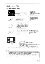
The F395 can provide waveform displays of signals from a strain gauge type sensor and
displacement sensor. The waveform display procedures are as follows.
(See "7-4. X/Y-axis Setting by Operation Mode and Input CH" P41.):
1. Connect a strain gauge type sensor (and displacement sensor) with the F395.
(See "4-1-1. Analog Input / Output Connection" P21.)
2. Perform calibration. (See "5. Methods of Calibration" P31.)
3. Set each parameter for waveform display.
(See "9. Method of Starting Measurement" P43, and "16-2-9. Level Axis Select /
Waveform Start Level / Waveform Termination Level / Hold Start Level" P113.)
4. Check to see if a waveform is displayed for the set conditions.
1-3. Multi-Hold Procedures
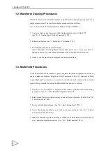
In the Multi-Hold mode, necessary points are detected in the displayed waveform to
make a judgment such as a High/Low Limit Comparison. Up to 32 channels of Hold
types, High and Low Limits, etc., can be stored, which can be switched by external
signals. The procedures for using the Multi-Hold function are as follows:
1. Check to see if a waveform is displayed in accordance with the waveform drawing
procedures. (See "1-2. Waveform Drawing Procedures" P3.)
2. Select a hold function so that necessary points in the waveform can be held. (See "10-
3. Carry out Multi-Hold settings. (See "16-2. Each Setting Item" P103.)
4. Select the channel number(s) you want to control externally. (See "4-3. Control
5. Input T/H and H/M signals in accordance with the selected hold function, and check to
see if operation is performed as set. (See "10-3. Hold Functions" P48.)
Содержание f395
Страница 1: ...Operation Manual F395 DYNAMIC FORCE PROCESSOR 10 Apr 2012 Rev 1 12...
Страница 167: ...21 Outer Dimensions 153 21 Outer Dimensions Unit mm 3 3 5 5 Rear Front Side Panel cut dimensions...
Страница 180: ...Unipulse Corporation 9 11 Nihonbashi Hisamatsucho Chuo ku Tokyo 103 0005 Tel 81 3 3639 6120 Fax 81 3 3639 6130...


