4.Methods of Connection
21
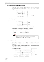
4-1-1. Analog Input / Output Connection
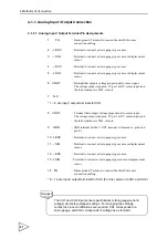
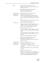
4-1-1-1. Analog Input / Output Terminal Pin Assignments
1
FG
:
Frame ground. Terminal to connect the shield of sensor
connection cabling.
2
+
EXC
:
Terminal to connect a strain gauge type sensor.
3
-
SIG
:
Terminal to connect a strain gauge type sensor or displacement
sensor.
4
-
EXC
:
Terminal to connect a strain gauge type sensor.
5
+
SIG
:
Terminal to connect a strain gauge type sensor or displacement
sensor.
6 V-OUT
:
Terminal that outputs voltage proportional to sensor input.
The voltage output is approx. 2V per 1mV/V sensor input, and
the load resistance is 5k
Ω
or more
7
N.C
* 1 ~ 6 are input / output terminals for CH1.
8 V-OUT
:
Terminal that outputs voltage proportional to sensor input.
The voltage output is approx. 2V per 1mV/V sensor input, and
the load resistance is 5k
Ω
or more.
9
GND
:
GND terminal for the V-OUT terminal. (Common to pin 6 and
pin 8.)
10
+
EXC
:
Terminal to connect a strain gauge type sensor.
11
-
SIG
:
Terminal to connect a strain gauge type sensor or displacement
sensor.
12
-
EXC
:
Terminal to connect a strain gauge type sensor.
13
+
SIG
: Terminal to connect a strain gauge type sensor or displacement
sensor.
14
FG
:
Frame ground. Terminal to connect the shield of sensor
connection cabling.
* 8 ~ 14 are input / output terminals for CH2. (Pin 9 is common to CH1 and CH2.)
The CH1 and CH2 input sensor specifications (strain gauge/current/
voltage) are factory-shipped settings. For changing the settings,
contact us since modifications are required. CH1 corresponds to a
strain gauge, and CH2 corresponds to voltage as a standard.
Request
Содержание f395
Страница 1: ...Operation Manual F395 DYNAMIC FORCE PROCESSOR 10 Apr 2012 Rev 1 12...
Страница 167: ...21 Outer Dimensions 153 21 Outer Dimensions Unit mm 3 3 5 5 Rear Front Side Panel cut dimensions...
Страница 180: ...Unipulse Corporation 9 11 Nihonbashi Hisamatsucho Chuo ku Tokyo 103 0005 Tel 81 3 3639 6120 Fax 81 3 3639 6130...

