


TURN SIGNAL LAMPS FRONT AND REAR
l
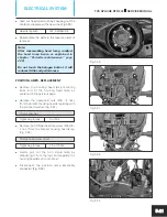
The DC output from the ignition lock is
connected to the switch turn signal through a
electronic flasher unit mounted below the seat
assembly near the battery. (Fig. 5.25)
l
The DC output wire orange (Or) from the
ignition lock is connected to the flasher unit
and the output from the flasher unit is
connected to the switch turn signal through a
light blue wire (Lbl).
l
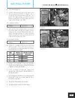
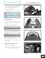
The switch turn signal is located on the switch
assembly handle LH. (Fig. 5.26)
l
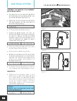
Inspect the switch for continuity with the
pocket tester.
Pocket tester
SWITCH POSITION
V
LbI
Lg
TO LEFT ( )
O
O
PRESS RELEASE
O
TO RIGHT( )
O
O
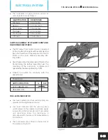
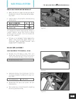
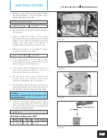
GEAR POSITION SENSOR
l
The gear position sensor is mounted on the
crankcase assembly LH below the cover
engine sprocket. (Fig. 5.27)
l
Gear position sensor senses the exact
position of the gear and generates the
resistance accordingly. These resistance are
sent to the digital speedometer and the TCI
unit through a white green wire (WG). To
measure the resistance level of gear position
sensor at various position follow the procedure
given below:
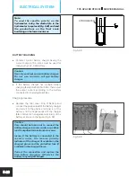
l
Set the pocket tester at 20k ohms position.
Pocket tester
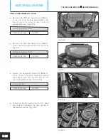
l
Disconnect the gear position sensor’s socket
form wiring harness.
l
Connect pocket tester’s ‘+ve‘ lead to the
green white wire (GW) of gear position sensor
and ‘–ve‘ lead to body earth. (Fig. 5.28)
Fig. 5.25
Fig. 5.26
Fig. 5.27
Fig. 5.28
TVS APACHE RTR 200
SERVICE MANUAL
ELECTRICAL SYSTEM
5-12


