


TCI UNIT
l
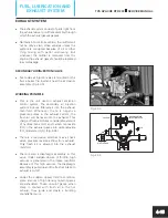
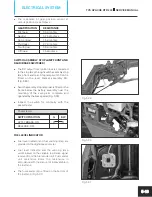
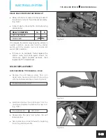
TCI unit (transistor control unit) is placed below
the fuel tank assembly near the battery. TCI
unit can be checked by doing a good (or) bad
analysis (replacing existing with a new).
(Fig.5.14
)
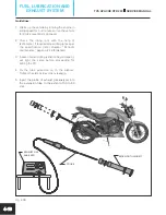
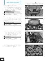
THERMAL SENSOR
l
A thermal sensor fixed on the cylinder block to
sense the engine temperature and give input
to the TCI unit in the form of resistance.
(Fig. 5.15) Check the resistance of the thermal
sensor in the following manner:
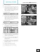
l
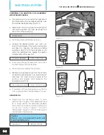
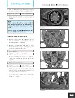
Set the pocket tester at 20k ohms position.
Pocket tester
l
Disconnect the thermal sensor coupler from
main wiring harness. Connect the pocket
tester’s ‘+ve’ lead to the yellow red (YR) wire
and ‘–ve’ lead to the white red (WR) of the
thermal sensor coupler and measure the
resistance when engine in cold condition.
(Fig. 5.16)
Resistance
3.0 ~ 14k ohms
l
If the resistance measured is not within the
specified limit, replace the thermal sensor with
a new one.
Fig. 5.14
Fig. 5.15
Fig. 5.16
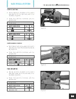
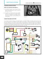
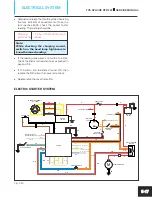
LIGHTING SYSTEM
The lighting system consists of magneto assembly, regulator cum rectifier unit (RR unit), battery, ignition lock, fuse
10A (head lamp), TCI unit and control switches. The working of lighting system of the TVS Apache RTR 200 4V are as
follows. (Fig. 5.17)
A DC output from the battery is connected to a 10A fuse (head lamp) through the ignition lock. The output of the 10A
fuse is connected to the TCI unit. When the ignition lock is turned ‘ON’, one more DC output from the lock is
supplied to TCI unit, switch lighting, switch beam control and the pass-by switch.
When the switch lighting knob is slid to the ‘PO’ position, the output DC current from the switch is supplied to the
position lamps and the tail lamp.
TVS APACHE RTR 200
SERVICE MANUAL
ELECTRICAL SYSTEM
5-7


