920.1020.12
24
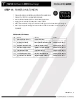
STEP 11:
POWER ON & TUNE-IN
•
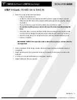
Ensure all wiring is complete according to the application
•
Ensure the 120 VAC is connected and secure
•
Ensure Off-On-Hold Switch is in the middle (0) position
•
Apply power and observe the LED’s at the control
•
The control will not accept an activation until approx. 8 seconds after powering on
•
The control will not initially activate the door until an activation, such as input 10, is
triggered
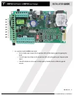
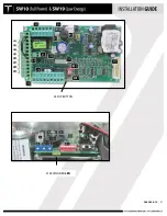
I/O Board LED Status
LED
LED ON
LED OFF
NOTES
LD1
Accessories power is present
No accessories power
LD2
Active internal opening command
Internal opening command inactive
Indicates status of input 10
LD3
Active external opening
command
External opening command inactive
Indicates status of input 11
LD4
Emergency command inactive
Emergency command active
Indicates status of input 12
LD5
Secondary Activation inactive
Secondary Activation command
active
Indicates status of input 13
LD6
Stop command inactive
Stop command active
Indicates status of input 14
LD7
In active
Inactive
Inactive
LD8
Fire Alarm command is active
Fire Alarm command inactive
Indicates status of input 16
LD9
Overhead Presence Command
Active
Overhead Presence Command
Inactive
Indicates status of input 17
Содержание SW10
Страница 11: ...920 1020 12 11 PUSH ARM ...
Страница 27: ...920 1020 12 27 SETUP BUTTON FLASHING RED LED ...
Страница 33: ...920 1020 12 33 APPENDIX WIRING DIAGRAMS SIMULTANEOUS PAIRS ...
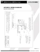
Страница 35: ...920 1020 12 35 APPENDIX WIRING DIAGRAMS ELECTRIC LOCK APPLICATION ...
Страница 36: ...920 1020 12 36 APPENDIX WIRING DIAGRAMS SW10 PAIR WITH BEA PARALLAX SYSTEM ...
Страница 37: ...920 1020 12 37 APPENDIX WIRING DIAGRAMS SW10 Single Pair WIth BEA LZR Microscan Sensors ...
Страница 38: ...920 1020 12 38 APPENDIX WIRING DIAGRAMS SW10 Single With Push Plates Torpedo Sensors For Secondary Activation ...
Страница 42: ...920 1020 12 42 APPENDIX TUCKER LOGO ...


