920.1020.12
28
TROUBLESHOOTING
Door will not open
•
Check On-Off switch for proper position
•
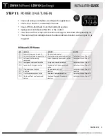
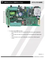
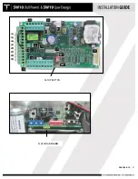
Check LED status for LD 5, 6, and 7. If any of these LED’s are OFF, the
door will not open. They require a normally closed circuit.
•
Launch a new setup – see page 26
•
Check status of emergency input 12
•
Door has traveled close past the 0 degree position
Door will not close
•
Check status of LEDs” LD2, 3, 4, 8 on the I/O board.
•
If any of the LED’s are ON, check the associated input
Door will not reach its full open or
closed position
•
Check the mechanical stops on the operator for proper adjustment
(see page 16)
Slow flashing red LED (LD2) at the
Adjustment Control Board
•
Indicates a possible fault in the control.
o
Check LED status for the other inputs. This will identify if any
inputs are currently active.
•
Indicates a potential faulty setup.
o
Loose or incorrect motor connection
o
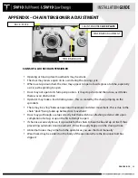
Possible loose chain tensioner - refer to Appendix for chain
tensioner adjustment procedures.
o
Launch a new setup. If problem repeats and there are no
other discrepancies noted, replace the operator/control sub-
assembly.
Door closes too fast at last 5 to 10
degrees of closing
•
Ensure dip switch 8 is OFF.
•
Ensure there is no binding of the door as it is closing through the last
few degrees of closing. If binding exists (from a tight bottom sweep,
for example), correct the condition and then re-launch a new setup.
JOB DOCUMENTATION & CLOSEOUT
•
Upon completion of the installation, provide the following to the Owner or their assigned
agent:
o
Completed & signed work ticket. Be certain to record any serial numbers for items
that were replaced.
o
Completed and signed copy of the AAADM inspection form
o
AAADM Owner’s Manual
•
Additionally, advise the Owner of the work that was performed and ask if there are any
other doors that may require service.
Содержание SW10
Страница 11: ...920 1020 12 11 PUSH ARM ...
Страница 27: ...920 1020 12 27 SETUP BUTTON FLASHING RED LED ...
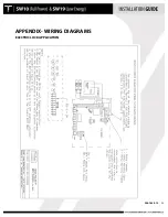
Страница 33: ...920 1020 12 33 APPENDIX WIRING DIAGRAMS SIMULTANEOUS PAIRS ...
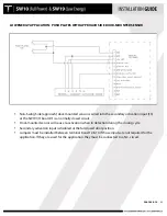
Страница 35: ...920 1020 12 35 APPENDIX WIRING DIAGRAMS ELECTRIC LOCK APPLICATION ...
Страница 36: ...920 1020 12 36 APPENDIX WIRING DIAGRAMS SW10 PAIR WITH BEA PARALLAX SYSTEM ...
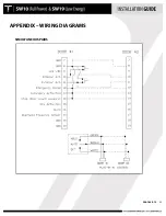
Страница 37: ...920 1020 12 37 APPENDIX WIRING DIAGRAMS SW10 Single Pair WIth BEA LZR Microscan Sensors ...
Страница 38: ...920 1020 12 38 APPENDIX WIRING DIAGRAMS SW10 Single With Push Plates Torpedo Sensors For Secondary Activation ...
Страница 42: ...920 1020 12 42 APPENDIX TUCKER LOGO ...


