920.1020.12
39
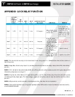
APPENDIX- LOCK RELAY FUNCTION
AUTO-OFF-
HOLD
SELECTOR
SWITCH
STATUS
DIP
SWITCH
3
INPUT
10
INPUT
11
LOCK RELAY STATUS
(door closed)
OPERATION
REMARKS
Line 1
AUTO
OFF
Active
Active
DE-Energized
Upon activation (10 or
11), lock relay energizes
and door opens
This is typically the
desired operation. If it
is necessary to shut off
all activation when
selector switch is OFF
AND keep door locked,
place dip switch 3 ON
and see Note #3.
Line 2
OFF
OFF
Inactive
Inactive
Energized
Placing the selector
switch to OFF unlocks
the door and remains
unlocked. All activation
is disabled.
Not typical for US
market. See Remarks
on Line #2.
Line 3
OFF
ON
Active
Inactive
DE-Energized
Upon activation (10),
lock relay energizes and
door opens. This serves
as an "Exit Only"
function. Input 11 is
disabled.
Typical for exit only
Line 4
AUTO
ON
Active
Active
DE-Energized
Upon activation (10 or
11), lock relay energizes
and door opens.
Typical for 2-way traffic
NOTE 1:
The most common setup is Line 3 & 4(above). In this setup, input 11 is disabled when the selector switch is in
the OFF position.
NOTE 2:
Regardless of lock setup, Input 13 (secondary activation) functions normally and will shut off at closed-door
position.
NOTE 3:
If it is desired to keep door locked AND shut off ALL activation when selector switch is OFF, place dip switch 3
ON AND tie all activation into Input 11.
NOTE 4:
Only electric strikes that are DC operated should be used. AC strikes that buzz will maintain the buzzing noise
until door gets fully closed again. The lock voltage is applied at activation and not released until the next closed door
position.
NOTE 5:
When selector switch is placed in Hold-Open position, lock relay remains energized.
NOTE 6:
If desired lock performance is beyond capability of the SW10 control, Tucker Auto-Mation recommends the
use of a BEA BR-3 Module.
Содержание SW10
Страница 11: ...920 1020 12 11 PUSH ARM ...
Страница 27: ...920 1020 12 27 SETUP BUTTON FLASHING RED LED ...
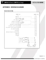
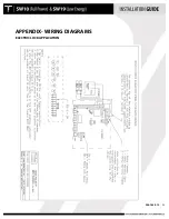
Страница 33: ...920 1020 12 33 APPENDIX WIRING DIAGRAMS SIMULTANEOUS PAIRS ...
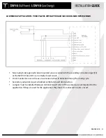
Страница 35: ...920 1020 12 35 APPENDIX WIRING DIAGRAMS ELECTRIC LOCK APPLICATION ...
Страница 36: ...920 1020 12 36 APPENDIX WIRING DIAGRAMS SW10 PAIR WITH BEA PARALLAX SYSTEM ...
Страница 37: ...920 1020 12 37 APPENDIX WIRING DIAGRAMS SW10 Single Pair WIth BEA LZR Microscan Sensors ...
Страница 38: ...920 1020 12 38 APPENDIX WIRING DIAGRAMS SW10 Single With Push Plates Torpedo Sensors For Secondary Activation ...
Страница 42: ...920 1020 12 42 APPENDIX TUCKER LOGO ...

