background image

Operator’s Manual

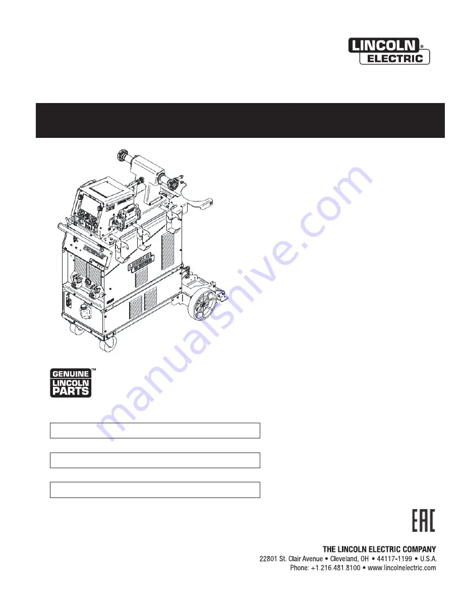
PIPEFAB 

 WELDING SYSTEM

Register your machine:   

www.lincolnelectric.com/registration


Authorized Service and Distributor Locator:   

www.lincolnelectric.com/locator


IM10549


e

t

D


e

u

s

s


Jul - 20

 © Lincoln Global, Inc.  All Rights Reserved.

For use with machines having Code Numbers: 

POWER SOURCE: 12858, 13010 
FEEDER: 12929

Need Help? Call 1.888.935.3877  

to talk to a Service Representative


Hours of Operation:  

8:00 AM to 6:00 PM (ET) Mon. thru Fri.


After hours?  

Use “Ask the Experts” at lincolnelectric.com 
A Lincoln Service Representative will contact you  
no later than the following business day.


For Service outside the USA:  

Email: [email protected]

Save for future reference   

Date Purchased 

Code: (ex: 10859) 

Serial: (ex: U1060512345)


*

REMOTE UI: 12938

Содержание PIPEFAB CE

Страница 1: ...Code Numbers POWER SOURCE 12858 13010 FEEDER 12929 Need Help Call 1 888 935 3877 to talk to a Service Representative Hours of Operation 8 00 AM to 6 00 PM ET Mon thru Fri After hours Use Ask the Experts at lincolnelectric com A Lincoln Service Representative will contact you no later than the following business day For Service outside the USA Email globalservice lincolnelectric com Save for future...

Страница 2: ...N A LARGE ROOM OR OUTDOORS natural ventilation may be adequate if you keep your head out of the fumes See below USE NATURAL DRAFTS or fans to keep the fumes away from your face If you develop unusual symptoms see your supervisor Perhaps the welding atmosphere and ventilation system should be checked WEAR CORRECT EYE EAR BODY PROTECTION PROTECT your eyes and face with welding helmet properly fitted...

Страница 3: ...ot engine parts and igniting Do not spill fuel when filling tank If fuel is spilled wipe it up and do not start engine until fumes have been eliminated 1 d Keep all equipment safety guards covers and devices in position and in good repair Keep hands hair clothing and tools away from V belts gears fans and all other moving parts when starting operating or repairing equipment 1 e In some cases it ma...

Страница 4: ...rm to ANSI Z87 I standards 4 b Use suitable clothing made from durable flame resistant material to protect your skin and that of your helpers from the arc rays 4 c Protect other nearby personnel with suitable non flammable screening and or warn them not to watch the arc nor expose themselves to the arc rays or to hot spatter or metal FUMES AND GASES CAN BE DANGEROUS 5 a Welding may produce fumes a...

Страница 5: ...ent passing through lifting chains crane cables or other alternate circuits This can create fire hazards or overheat lifting chains or cables until they fail 6 h Also see item 1 c 6 I Read and follow NFPA 51B Standard for Fire Prevention During Welding Cutting and Other Hot Work available from NFPA 1 Batterymarch Park PO box 9101 Quincy MA 022690 9101 6 j Do not use a welding power source for pipe...

Страница 6: ...s et non inflamma bles 4 Des gouttes de laitier en fusion sont émises de l arc de soudage Se protéger avec des vêtements de protection libres de l huile tels que les gants en cuir chemise épaisse pantalons sans revers et chaussures montantes 5 Toujours porter des lunettes de sécurité dans la zone de soudage Utiliser des lunettes avec écrans lateraux dans les zones où l on pique le laitier 6 Eloign...

Страница 7: ...nt used for calibration or measurement g the immunity of other equipment in the environment The user shall ensure that other equipment being used in the environment is compatible This may require additional protection measures h the time of day that welding or other activities are to be carried out The size of the surrounding area to be considered will depend on the structure of the building and o...

Страница 8: ...GE SELECTION A 23 PIPEFAB POWER SOURCE CONNECTOR LOCATIONS A 23 PIPEFAB FEEDER CONNECTOR LOCATIONS A 24 CONNECTION DIAGRAM A 24 RECOMMENDED WORK CABLE SIZES FOR ARC WELDING A 27 GENERAL GUIDELINES A 27 CABLE INDUCTANCE AND ITS EFFECTS ON WELDING A 28 REMOTE SENSELEAD SPECIFICATIONS A 28 VOLTAGE SENSING CONSIDERATIONS FOR MULTIPLE ARC SYSTEMS A 31 CONTROL CABLECONNECTIONS A 32 FEEDER CONNECTORS A 3...

Страница 9: ...ANCE D 1 CALIBRATIONSPECIFICATION D 2 WIRING DIAGRAM AND DIMENSION PRINT SECTION E PARTSLIST PARTS LINCOLNELECTRIC COM Content details may be changed or updated without notice For most current Instruction Manuals go to parts lincolnelectric com TABLE OF CONTENTS ...

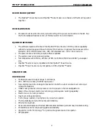
Страница 10: ...nc onality the dedicated process bu ons and individual process memories make switching from one process to another simple and intui ve Superior arc performance simplicity and flexibility are at the core of the PipeFab Being an advanced so ware controlled system the PipeFab is readily user updateable with free so ware from www powerwaveso ware com allowing it to take advantage of the latest and grea...

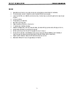
Страница 11: ...1500 4 K1500 5 and K489 7 gun adapter kits PipeFab Feeder is only compatible with the PipeFab Power Source PipeFab Power Source is only compatible with the PipeFab Feeder DESIGN FEATURES POWER SOURCE Multiple process DC output range 5 400 Amps 200 600 VAC 3 phase 50 60Hz input power New and Improved Line Voltage Compensation holds the output constant over wide input voltage fluctuations Utilizes n...

Страница 12: ...ll bushing inlet guide High resolution encoder on the motor 7 digital user interface display Displays voltage trim wire feed speed amps process settings advanced settings and more Quick select buttons for switching processes Center push to select encoder to navigate menus on screen Total of 24 memories 4 dedicated memories per process TIG and STICK and 4 dedicated memories per process and side MIG...

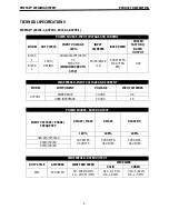
Страница 13: ... 550 WATTS MAX FAN ON 0 94 K3732 1 WIRE FEEDER INPUT VOLTAGE AND CURRENT MODEL COMPONENT VOLTAGE INPUT AMPERES K3735 1 WIRE DRIVE 40 VDC 9 A USER INTERFACE 40 VDC 1 A POWER SOURCE RATED OUTPUT INPUT VOLTAGE PHASE FREQUENCY GMAW FCAW SMAW GTAW DC 100 100 100 380 415 3 50 60 400 AMPS 34 VOLTS 400 AMPS 36 VOLTS 400 AMPS 26 VOLTS 460 3 50 60 575 3 50 60 WIRE FEEDER RATED OUTPUT DUTY CYCLE AMPERES WIRE...

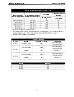
Страница 14: ...S National electrical Code 2 Also called inverse time or thermal magnetic circuit breakers circuit breakers that have a display in tripping action that decreases as the magnitude of the current increases 3 Type SO cord or similar in 30 C ambient AGENCY MARKINGS MODEL MARKET CONFORMITY MARK STANDARD K3731 1 US AND CANADA CCSAUL CAN CSA E60974 1 ANSI IEC 60974 1 K3732 1 US AND CANADA CCSAUL CAN CSA ...

Страница 15: ... LBS 320 MM 500 MM 424 MM 24 7 KG WIRE REEL STAND 13 8 IN 22 0 IN 28 2 IN 25 5 LBS 351 MM 559 MM 716 MM 11 6 KG PIPEFAB FEEDER AND WIRE REEL STAND 14 5 IN 22 0 IN 30 2 IN 80 0 LBS 368 MM 550 MM 767 MM 36 3 KG COMPLETE SYSTEM 53 2 IN 30 9 IN 48 8 IN 500 LBS 1351 3 MM 784 9 MM 1239 5 MM 226 KG TEMPERATURE RANGES MODEL OPERATING RANGE STORAGE RANGE POWER SOURCE 4 F TO 104 F 20 C TO 40 C 40 F TO 185 F...

Страница 16: ...ectrode when welding output is ON Wire feeder may be connected to a piece of automatic equipment that may be remotely controlled Do not operate with covers panels or guards removed Do not let the electrode or wire spool touch the wire feeder housing Insulate yourself from the work and ground Always wear dry insulating gloves The lift bail is insulated from the wire feeder enclosure If an alternate...

Страница 17: ... with a steel plate at least 060 1 6mm thick which shall extend not less than 5 90 150mm beyond the equipment on all sides The PipeFab feeder is rated IP2X and is suitable for indoor use For best wire feeding performance place the PipeFab Feeder on a stable and dry surface Do not submerge the feeder This equipment is for industrial use only and it is not intended for use in residential locations w...

Страница 18: ...PIPEFAB WELDING SYSTEM INSTALLATION A 3 FIGURE A 1 ...

Страница 19: ... has the water cooler installed In the below images the water cooler is installed Note that hardware in not necessary for the installation of the feeder Hardware is included if desired 1 Position the Wire Reel Stand onto the Power Source Ensure the lift bale is routed through the lift bale cutout and the Spindles are towards the rear of the machine FIGURE A 2 2 Install the Cable Management bracket...

Страница 20: ...nsure the feet of the feeder engage with the feet cutouts in the Wire Reel Stand FIGURE A 4 4 If desired the PipeFab feeder and cable management brackets can be hard mounted to the wire reel stand using the provided hardware and L brackets as shown below This is optional as these were designed to align securely without hardware ...

Страница 21: ...PIPEFAB WELDING SYSTEM INSTALLATION A 6 FIGURE A 5 L BRACKET INSTALLATION FIGURE A 6 CABLE MANAGEMENT BRACKET MOUNTING ...

Страница 22: ... the outer wire guide 4 Remove drive rolls by pulling straight out It may be necessary to wiggle the drive roll to free it from the snap ring 5 Remove the inner wire guide 6 Install the new inner wire guide with the arrow poin ng in the direc on of wire travel 7 Install the drive rolls and outer wire guide 8 Close the wire drive door and adjust the pressure se ng accordingly ...

Страница 23: ... the gun against a solid object that is electrically isolated from the welder output and press the gun trigger for several seconds 2 If the wire birdnests or jams the drive roll pressure is too high Reduce the pressure by one turn of the knob run new wire through the gun and repeat step 1 3 If the only result is slippage disconnect the gun and pull the gun cable forward about 6 150mm There should ...

Страница 24: ... INSTALLATION 1 Turn power OFF at the welding power source 2 Using a Phillips screwdriver remove the screw lock washer and washer securing the gun adapter cover Remove the gun adapter cover FIGURE A 9 3 Using a wrench remove the bolt securing the electrode lead to the gun adapter FIGURE A 10 ...

Страница 25: ...se a 1 8 hex key loosen the set screw securing the gun adapter FIGURE A 11 5 Using a Phillips screwdriver remove the sense lead FIGURE A 12 6 If a gas hose is a ached to the gun adapter use pliers to remove the hose clamp and remove the gas hose ...

Страница 26: ...apter 9 If required assemble the gas hose to the gun adapter or the fi ng on the feed plate and secure with a hose clamp 10 Assemble the gun adapter to the wire drive Tighten the set screw once the gun adapter is at a 90 angle 11 Bolt the electrode lead to the gun adapter making sure to route the lead straight down FIGURE A 14 Wire size Number of grooves in guide tube 023 045 0 6 1 2 mm 1 045 1 16 ...

Страница 27: ...te gun adapters requires a K3344 1 Standard 4 gun adapter to be installed in the wire drive 1 Turn power OFF at the welding power source 2 Using a Phillips screwdriver loosen the screw securing the gun adapter cover Remove the gun adapter cover FIGURE A 16 3 Using a wrench remove the bolt securing the electrode lead to the gun adapter 4 Using pliers remove the hose clamp and hose from the gun adap...

Страница 28: ...AB WELDING SYSTEM INSTALLATION A 13 5 Bolt the electrode lead to the gun adapter making sure to route the lead straight down FIGURE A 17 6 Assemble the gun adapter cover and secure with the screw FIGURE A 18 ...

Страница 29: ...ure with the set screw FIGURE A 20 9 Slide the Oxo or FastMate gun adapter into the wire drive and secure with the thumb screw 10 For FastMate gun adapters connect the trigger pigtail to the connector on the front of the feeder Wire size Number of grooves in guide tube 023 045 0 6 1 2 mm 1 045 1 16 1 2 1 6 mm 2 1 16 5 64 1 6 2 0 mm 3 068 7 64 2 0 2 8 mm 4 ...

Страница 30: ...ATING THE WIRE DRIVE 1 Turn power OFF at the welding power source 2 Locate the socket head cap screw at the bo om of the wire drive Loosen but do not remove the screw FIGURE A 21 3 Rotate the wire drive to the desired posi on and ghten the screw ...

Страница 31: ... Inform your gas supplier of this condi on Oil or grease in the presence of high pressure oxygen is explosive 3 Stand to one side away from the outlet and open the cylinder valve for an instant This blows away any dust or dirt which may have accumulated in the valve outlet 4 A ach the flow regulator to the cylinder valve and ghten the union nut s securely with a wrench NOTE If connec ng to 100 CO2 ...

Страница 32: ...installs underneath the wire drive 1 Turn power OFF at the welding power source 2 Install the quick disconnect fi ngs to the plas c bracket by holding the rear nut sta onary and spinning the fi ng 3 Cut the tubing to the desired length and then install the tubing and hose clamps to the fi ngs FIGURE A 22 ...

Страница 33: ...n power OFF at the welding power source 2 Squeeze the release bar on the retaining collar and remove it from the spindle FIGURE A 23 3 Place the spool on the spindle aligning the spindle brake pin with one of the holes in the back side of the spool Be certain the wire feeds off of the spool in the proper direc on FIGURE A 24 4 Re install the retaining collar with the metal bar engaging one of the g...

Страница 34: ...nd symbol is located next to the input power connec on block See your local and na onal electrical codes for proper grounding methods HIGH FREQUENCY PROTECTION Locate the PipeFab away from radio controlled machinery The normal opera on of the PipeFab may adversely affect the opera on of RF controlled equipment which may result in bodily injury or damage to the equipment INPUT CONNECTION Use a three...

Страница 35: ...WER CONNECTION POWER CONNECTION BLOCK CONNECT EACH PHASE OF A THREE PHASE CONDUCTOR HERE GROUND CONNECTION CONNECT GROUND LEAD PER LOCAL AND NATIONAL ELECTRIC CODE INPUT CORD STRAIN RELIEF ROUTE INPUT CORD THROUGH RELIEF AND TWIST NUT TO TIGHTEN FIGURE A 27 K3732 1 INPUT POWER CONNECTION POWER CONNECTION BLOCK CONNECT EACH PHASE OF A THREE PHASE CONDUCTOR HERE GROUND CONNECTION CONNECT GROUND LEAD...

Страница 36: ...aller than recommended may result in nuisance shut offs from welder inrush currents even if the machine is not being used at high currents INPUT VOLTAGE SELECTION The PipeFab automa cally adjusts to work with different input voltages No reconnect switch se ngs are required The PipeFab ON OFF switch is not intended as a service disconnect for this equipment Only a qualified electrician should connect ...

Страница 37: ... POWER SOURCE CONNECTOR LOCATIONS CASE FRONT LOCATIONS FIGURE A 27 1 Power Switch 2 Status LED 3 Thermal LED 4 Status II LED 5 12 Pin Connector 6 Sense Lead Connector 7 Work Weld Output Terminal 8 TIG Weld Output Terminal 9 S ck Weld Output Terminal ...

Страница 38: ...PIPEFAB WELDING SYSTEM INSTALLATION A 23 CASE BACK LOCATIONS FIGURE A 28 1 TIG Gas Input Solenoid 2 Ethernet 3 MIG Weld Output Stud 4 ArcLink Connector 5 40 Volt Circuit Breaker 6 Input Power Cord ...

Страница 39: ... Solenoid CONNECTION DIAGRAM The PipeFab system was design such that all connec ons can be maintained when switching welding processes There is no longer the need to changeover torches and welding cables between processes The PipeFab Power Source will automa cally change polarity and ac ve output terminals based on the selected process This selec on is made on the user interface of the PipeFab Fee...

Страница 40: ...I into the PipeFab Feeder 12 pin located on the back of the feeder The remote UI is designed for hard automa on setups with a manipulator FIGURE A 31 The Remote UI is to be connected to the system in addi on to the UI mounted in the Wire Feeder When a remote UI is connected only one UI will be ac ve at a me In order to ac vate an inac ve UI press any bu on ...

Страница 41: ...utoma on setups with or without a Remote UI This is a toggle switch and lead assembly which connects to the appropriate gun trigger connec on to start and stop the wire feeder Turn the switch ON to start welding at the set parameters Turn the switch OFF to stop welding FIGURE A 32 CONNECTION DIAGRAM OF REMOTE TRIGGER ...

Страница 42: ...ables in close proximity to one another to minimize the loop area and therefore the inductance of the weld circuit Always weld in a direc on away from the work ground connec on Table A 1 shows copper cable sizes recommended for different currents and duty cycles Lengths s pulated are the distance from the welder to work and back to the welder again Cable sizes are increased for greater lengths prim...

Страница 43: ...ive lengths and do not coil excess cable For long work piece lengths a sliding ground should be considered to keep the total welding loop length as short as possible REMOTE SENSE LEAD SPECIFICATIONS VOLTAGE SENSING OVERVIEW The best arc performance occurs when the PipeFab has accurate data about the arc condi ons Depending upon the process inductance within the electrode and work cables can influen...

Страница 44: ...NAL 3 RECOMMENDED FOR CABLES LONGER THAN 75 FT GTAW VOLTAGE SENSE AT STUDS VOLTAGE SENSE AT STUDS SMAW VOLTAGE SENSE AT STUDS VOLTAGE SENSE AT STUDS 1 The electrode voltage sense lead 67 is automa cally enabled by the weld process and integral to the 5 pin ArcLink control cable K1543 xx 2 When a work voltage sense lead 21 is connected the power source will automa cally switch over to using this fe...

Страница 45: ...ol panel by using the K940 Sense Lead Kit It must be a ached to the work as close to the weld as prac cal but out of the weld current path For more informa on regarding the placement of remote work voltage sense leads see in this sec on en tled Voltage Sensing Considera ons for Mul ple Arc Systems NEGATIVE ELECTRODE POLARITY The PipeFab has the ability to automa cally change the polarity of the po...

Страница 46: ...If Sense Leads ARE Used Posi on the sense leads out of the path of the weld current Especially any current paths common to adjacent arcs Current from adjacent arcs can induce voltage into each others current paths that can be misinterpreted by the power sources and result in arc interference For longitudinal applica ons connect all work leads at one end of the weldment and all of the work voltage ...

Страница 47: ...mmunica on and power needs of the Power Wave Power Feed systems Most are designed to be connected end to end for ease of extension Generally it is recommended that the total length not exceed 200 61 m The use of nonstandard cables especially in lengths greater than 25 feet can lead to communica on problems system shutdowns poor motor accelera on poor arc star ng and low wire driving force wire fee...

Страница 48: ...vity module K4720 1 the PipeFab will be able to connect remotely wireless via a USB WIFI adapter customer must supply or wired through an Ethernet cable WELD CABLES COAXIAL FIGURE A 35 Coaxial welding cables are specially designed welding cables for STT and pulse welding Coaxial weld cables feature low inductance allowing fast changes in the weld current Regular cables have a higher inductance whi...

Страница 49: ...d the other end to the work piece Minimize the length of any work lead extension for best results 4 Insulate all connec ons TABLE A 4 RECOMMENDED CABLE SIZES RUBBER COVERED COPPER RATED 75 C AMPERES DUTY CYCLE COAXIAL CABLE LENGTH 0 TO 25 FT 25 TO 50 FT 50 TO 75 FT 75 TO 100 FT 250 300 350 100 60 60 1 1 1 0 1 1 1 0 1 1 1 1 0 Tabled values are for opera on at ambient temperatures of 40 C and below ...

Страница 50: ... WIRING 12 PIN CONNECTOR FOR PIPEFAB REMOTE UI A CAN LOW B CAN HIGH C NOT USED D NOT USED E NOT USED F NOT USED G NOT USED H NOT USED J 40 VDC COMMON K 40 VDC L NOT USED M NOT USED TRIGGER CONNECTOR 5 PIN TABLE A 6 PICTURE FUNCTION PIN WIRING 5 PIN TRIGGER CONNECTOR FOR PUSH ONLY GUNS A TRIGGER B NOT USED C TRIGGER D N A E N A ...

Страница 51: ...PEFAB WELDING SYSTEM INSTALLATION A 36 ARCLINK CONNECTOR 5 PIN TABLE A 7 PICTURE FUNCTION PIN WIRING 5 PIN CONNECTOR FOR COMMUNICATION AND POWER A CAN B CAN C 67 ELECTRODE VOLTAGE SENSE D 40 VDC E COMMON ...

Страница 52: ... with skin or wet clothing Insulate yourself from work and ground Always wear dry insula ng gloves Do not operate with covers panels or guards removed or open FUMES AND GASES can be dangerous Keep your head out of fumes Use ven la on or exhaust to remove fumes from breathing zone WELDING SPARKS can cause fire or explosion Keep flammable material away ARC RAYS can burn Wear eye ear and body protec on...

Страница 53: ...DING AMPERAGE THERMAL INPUT POWER WELDING VOLTAGE SHIELDING GAS ON WIRE FEED SPEED ARC START PARAMETERS OFF TRIM ARC END PARAMETERS POSITIVE OUTPUT WORK DANGEROUS VOLTAGE NEGATIVE OUTPUT COLD FEED COOLER FRAME GROUND GAS PURGE STATUS U1 INPUT VOLTAGE SHIELDING GAS INLET OUTPUT I1 INPUT CURRENT SHIELDING GAS OUTLET PROTECTIVE GROUND ...

Страница 54: ...PIPEFAB WELDING SYSTEM OPERATION B 3 I2 OUTPUT CURRENT 4 STEP TRIGGER OPERATORS MANUAL CIRCUIT BREAKER CV PROCESS TIG PROCESS STICK PROCESS ...

Страница 55: ...ocedure to the Crater Procedure FCAW Weld process that uses gas shielded wire Gas Purge Turns on the gas solenoid for as long as the gas purge switch is held Gas Type Shielding gases that can be used Argon CO2 98 Ar 2 CO2 90 Ar 10 CO2 85 Ar 15 CO2 80 Ar 20 CO2 75 Ar 25 CO2 HF TIG star ng method HF turns on to help start the arc when output is enabled HF start is used when a non contact arc start m...

Страница 56: ...ocess uses either HF or Touch Start weld mode to begin welding Trim Adjusts the arc length FIGURE B 1 Ul marc Ul marc regulate the focus or shape of the arc Values greater than 0 0 increase the pulse frequency while decreasing the background current resul ng in a ght s ff arc best for high speed sheet metal welding Values less than 0 0 decrease the pulse frequency while increasing the background cu...

Страница 57: ...beyond the control of The Lincoln Electric Company affect the results obtained in applying these programs These variables include but are not limited to welding procedure plate chemistry and temperature weldment design fabrica on methods and service requirements The available range of a welding program may not be suitable for all applica ons and the builder user is and must be solely responsible fo...

Страница 58: ...ill ac vate the right wire drive The ac ve wire drive may also be selected by pulling the gun trigger on the le or right wire drive respec vely The green arrow on the top of either the le or right side of the user interface indicates the ac ve wire drive When the ac ve wire drive is switched all parameters of the ac ve drive from the last ac ve procedure are loaded into the display FIGURE B 3 ...

Страница 59: ...nt of the Remote UI The power source output remains OFF during Cold Feeding To set cold feed speed turn the le knob while holding the cold feed bu on FIGURE B 4 GAS PURGE Pressing the Gas Purge rocker switch turns on the gas solenoid for as long as the gas purge switch is held When connected to the PipeFab Remote UI gas purge may be ac ve by the rocker switch on the side of the feeder or the rocke...

Страница 60: ... system to TIG mode This will deac vate all outputs besides the TIG output 6 MIG Bu on Press to set the system to MIG mode This will deac vate all outputs besides the MIG output 7 FCAW Bu on Press to set the system to FCAW mode This will deac vate all outputs besides the FCAW output 8 Memory Bu ons Memories can be saved for each welding mode These can be accessed by touching the applicable memory ...

Страница 61: ... the More Se ngs to adjust the allowable ranges to be set by a remote 3 Electrode Type Selec on XX10 XX18 4 Arc Force Enter the More Se ngs to adjust the value Only displayed when set to a non zero value 5 Hot Start Enter the More Se ngs to adjust the value Only displayed when set to a non zero value 6 Output Indicator Note Output is ON at all mes in S ck process NOTE simplified home screens are us...

Страница 62: ...Selec on Touch Start HF 4 Post Flow Time Time that the shielding gas con nues to flow a er the arc has been terminated Only displayed when set to a non zero value 5 Pre Flow Time Time that the shielding gas con nues to flow before the arc has been started Only displayed when set to a non zero value 6 Output Indicator Output will be on in Touch Start mode without a remote Output will be off un l trigg...

Страница 63: ...vide ideal welding 2 Start Time Controls the voltage for a specified me at the beginning of the weld During that me the machine will ramp from the Start Procedure to the Welding Procedure 3 Crater Time Controls the voltage for a specified me at the end of the weld a er the trigger is released During the Crater me the machine will ramp from the Weld Procedure to the Crater Procedure 4 Current Se ngs ...

Страница 64: ...eed Speed Se ng Sets the desired wire feed speed use le knob to adjust 4 Voltage Se ng Sets the voltage use right knob to adjust 5 Wire Diameter Selec on 6 Gas Type Selec on 7 2 Step 4 Step Trigger Interlock Toggles between 2 Step and 4 Step Trigger Interlock 2 Step provides weld power and feeds wire only when the trigger is depressed 4 Step eliminates the need to hold the trigger while welding It...

Страница 65: ...eld power and feeds wire only when the trigger is depressed 4 Step eliminates the need to hold the trigger while welding It operates in 4 steps 1 Close trigger and establish welding arc 2 Release trigger and con nue welding 3 Reclose trigger near end of weld 4 Release trigger again to stop welding NOTE No symbol will be shown if 2 Step mode is ac ve 10 Ul marc Pinch Ul marc and Pinch regulate the ...

Страница 66: ...ing output turns on 4 Start Time Controls the WFS and Volts for a specified me at the beginning of the weld During the start me the machine will ramp from the Start Procedure to the preset Welding Procedure 5 Crater Time Controls the WFS and voltage for a specified me at the end of the weld a er the trigger is released During the Crater me the machine will ramp from the Weld Procedure to the Crater ...

Страница 67: ...lay wire feed speed metric or imperial 5 Water Cooler Opera on Determines when the op onal K3737 1 PipeFab Cooler will run not pictured 6 Advanced System Se ngs not pictured NOTE System Menu can only be accessed through the More Op ons menu 7 Weld Set Units Changes the weld set in use to be op mized for Imperial or metric units Machine reset is required for this change to take effect MIG and FCAW m...

Страница 68: ...M OPERATION B 17 ADVANCED SYSTEM SETTINGS FIGURE B 14 1 So ware Versions Allows access to a list of so ware components grouped by system component Also lists the IP address of the Ethernet port See Figure B 15 on page B 18 ...

Страница 69: ...he actual welding voltage and current will be displayed for the me specified in Weld Feedback Time or un l the next weld starts 3 Home Screen Choose between Simplified default or Advanced The Advanced Home Screen shows more details of parameters set by the user 4 Manage Restric ons Allows the user to create set or enter a Supervisor PIN Operator PIN and to view and change the Operator Restric ons En...

Страница 70: ... operator to only use processes and parameters stored in Memories In Memory Only Mode if no memory exists for a given process that process bu on is disabled when using the associated side of the feeder For example if Memory Only Mode is ON and no memories are configured for a FCAW process on the le feeder the machine cannot be put in FCAW mode when the le feeder is ac ve Memory Modifica ons Memory m...

Страница 71: ...of the screen Press the knob to select the highlighted op on 3 Wire Feed Speed Se ng Sets the desired wire feed speed use the le knob to adjust 4 Voltage Se ng Sets the voltage use the right knob to adjust 5 Wire Type Selec on 6 Wire Diameter Selec on 7 Gas Type Selec on 8 Synergic Voltage Indicator Nominal voltage is shown Lowering the voltage below nominal will move the bar to the le Raising the...

Страница 72: ...E B 18 1 Advanced se ngs will appear here Each weld process will have different se ngs The most common advanced se ngs are Pinch Arc Force Hot Start Pre Flow Time Post Flow Time 2 Step 4 Step Trigger and Ul marc Advanced se ngs will only be displayed when set to a non zero value ...

Страница 73: ...ICATOR FIGURE B 19 1 Current Se ng 2 Previous Se ng Indicator The do ed line will indicate where on the bar the most recent se ng was 3 Current Se ng Indicator Increasing the value will move the bar to the right decreasing the value will move the bar to the le ...

Страница 74: ...PIPEFAB WELDING SYSTEM OPERATION B 23 WELDING SCREEN FIGURE B 20 1 Output Ac ve 2 Feedhead Indicator MIG and FCAW modes only 3 Actual Current 4 Actual Voltage 5 Current Weld Se ngs ...

Страница 75: ... WELDING SYSTEM OPERATION B 24 BACK HOME BUTTONS FIGURE B 21 1 Back Bu on Selec ng the back bu on takes the system back one screen 2 Home Bu on Selec ng the home bu on takes the system back to the home screen ...

Страница 76: ... the LED will be lit if any se ngs are changed the LED will go out If the memory bu on is pressed again the se ngs will revert to the se ngs saved in the memory Four memories each can be saved in the S ck process TIG process MIG Le Feedhead MIG Right Feedhead FCAW Le Feedhead and FCAW Right Feedhead Memory usage with remotes If a TIG process is saved with a remote control connected the remote cont...

Страница 77: ...ouching the applicable memory bu on labeled one through four To save a memory hold the desired memory loca on down un l the screen indicates the memory is saved The remote UI has its own set of memories These are not shared with the memories stored in the wire feeder UI 6 USB Connector A USB drive can be inserted to upload download memories and update the user interface so ware 7 Feedhead Select S...

Страница 78: ...nd return to a typical welding screen Remove the USB s ck from the USB port New user interface so ware can be found at powerwaveso ware com WAVE CONTROL TABLE B 2 PROCESS WAVE CONTROL NAME EFFECT RANGE DESCRIPTION STICK ARC FORCE SOFT 10 0 TO CRISP 10 0 ARC FORCE ADJUSTS THE SHORT CIRCUIT CURRENT FOR A SOFT ARC OR FOR A FORCEFUL DRIVING ARC IT HELPS TO PREVENT STICKING AND SHORTING OF ORGANIC COAT...

Страница 79: ...PULSE FREQUENCY WHILE DECREASING THE BACKGROUND CURRENT RESULTING IN A TIGHT STIFF ARC BEST FOR HIGH SPEED SHEET METAL WELDING ULTIMARC VALUES LESS THAN 0 0 DECREASE THE PULSE FREQUENCY WHILE INCREASING THE BACKGROUND CURRENT FOR A SOFT ARC GOOD FOR OUT OF POSITION WELDING TIG NO WAVE CONTROLS AVAILABLE Arc Control OFF Medium Frequency and Width Arc Control 10 0 High Frequency Focused Arc Control ...

Страница 80: ...plest trigger opera on occurs with a 2 Step trigger and Start and Crater set to OFF For this sequence PREFLOW Shielding gas begins to flow immediately when the gun trigger is pulled RUN IN A er preflow me expires the power source regulates to the welding output and wire is advanced towards the work piece at the Run In WFS If an arc is not established within 2 0 seconds the wire feed speed will jump ...

Страница 81: ...ece at the Run In WFS If an arc is not established within 2 0 seconds the power source output and wire feed speed skips to the weld se ngs START Once the wire touches the work and an arc is established both the machine output and the wire feed speed ramp to the weld se ngs throughout the start me The me period of ramping from the start se ngs to the weld se ngs is called UPSLOPE WELD A er upslope ...

Страница 82: ...re touches the work and an arc is established both the machine output and the wire feed speed ramp to the weld se ngs throughout the start me The me period of ramping from the start se ngs to the weld se ngs is called UPSLOPE WELD A er upslope the power source output and the wire feed speed con nue at the weld se ngs CRATER DOWNSLOPE As soon as the trigger is released the wire feed speed and power...

Страница 83: ... the trigger to start feed of wire When arc is established the sequencer will begin START UPSLOPE If trigger is released during UPSLOPE and CRATER DOWNSLOPE is ac ve the machine will begin CRATER DOWNSLOPE and sloping down over the CRATER me regardless of when the trigger release occurred If the CRATER is disabled and the trigger is released during START UPSLOPE the sequencer will move to the BURN...

Страница 84: ...rlock adds to the welder s comfort when making long welds by allowing the trigger to be released a er an ini al trigger pull Welding stops when the trigger is pulled a second me and then released or if the arc is interrupted For this sequence PREFLOW Shielding gas begins to flow immediately when the gun trigger is pulled RUN IN A er preflow me expires the power source regulates to the welding output...

Страница 85: ...the power source output and wire feed speed skips to the weld se ngs START The power source welds at the start WFS and voltage un l the trigger is released UPSLOPE During upslope the power source output and the wire feed speed ramp to the weld se ngs throughout the start me The me period of ramping from the start se ngs to the weld se ngs is called UPSLOPE If the trigger is pulled before upslope i...

Страница 86: ...trigger release occurs during UPSLOPE the sequencer will jump to the BURNBACK to end the weld Example 2 Pull the trigger to start feed of wire When arc is established the sequencer will remain in START un l the trigger is released When the trigger is released UPSLOPE begins and con nues into WELD when the START mer is complete When the trigger is pulled again step 3 and CRATER DOWNSLOPE is ac ve D...

Страница 87: ...F 50 150 IN MIN TO WELD WFS RUN IN SETS THE WIRE FEED SPEED FROM THE TIME THE TRIGGER IS PULLED UNTIL AN ARC IS ESTABLISHED OR 2 5 SECONDS USE RUN IN FOR SOFTER ARC STARTS START TIME WFS AND VOLTS 0 10 0 SECONDS THE START PROCEDURE CONTROLS THE WFS AND VOLTS FOR A SPECIFIED TIME AT THE BEGINNING OF THE WELD DURING THE START TIME THE MACHINE WILL RAMP UP OR DOWN FROM THE START PROCEDURE TO THE PRES...

Страница 88: ... THE MACHINE WILL RAMP UP OR DOWN FROM THE WELD PROCEDURE TO THE CRATER PROCEDURE CRATER IS NOT COMMONLY USED WITH STT PROCESSES BURNBACK TIME AUTO 0 0 25 SECONDS THE BURNBACK TIME IS THE AMOUNT OF TIME THAT THE WELD OUTPUT CONTINUES AFTER THE WIRE FEEDING STOPS IT PREVENTS THE WIRE FROM STICKING IN THE PUDDLE AND PREPARES THE END OF THE WIRE FOR THE NEXT ARC START POSTFLOW TIME 0 60 0 SECONDS ADJ...

Страница 89: ...TE WORK CLAMP ELECTRODE HOLDER AND SAMPLE PACK OF MILD STEEL ELECTRODE K704 ACCESSORY KIT 400 AMP INCLUDES 35 FT 10 7 M 2 0 ELECTRODE CABLE WITH LUG 30 FT 9 1 M 2 0 WORK CABLE WITH LUGS HEADSHIELD FILTER PLATE WORK CLAMP AND ELECTRODE HOLDER TIG OPTIONS PRO TORCH TIG TORCHES A FULL LINE OF AIR COOLED AND WATER COOLED TORCHES AVAILABLE K963 4 HAND AMPTROL PROVIDES 25 FT 7 6 M OF REMOTE CURRENT CONT...

Страница 90: ...ROLL KITS CORED WIRES INCLUDES 4 KNURLED DRIVE ROLLS AND INNER WIRE GUIDE KP1505 035C 030 035 0 8 0 9 MM KP1505 045C 040 045 1 0 1 2 MM KP1505 052C 052 1 4 MM KP1505 1 16C 1 16 1 6 MM DRIVE ROLL KITS STEEL OR CORED WIRES INCLUDES 4 KNURLED DRIVE ROLLS AND INNER WIRE GUIDE KP1505 068 068 072 1 8 MM KP1505 5 64 5 64 2 0 MM DRIVE ROLL KITS ALUMINUM WIRE INCLUDES 4 POLISHED U GROOVE DRIVE ROLLS OUTER ...

Страница 91: ...AND LEAD KITS TABLE C 5 K NUMBER DESCRIPTION PURPOSE CONTROL CABLES K1543 XX CONTROL CABLE MALE 5 PIN TO FEMALE 5 PIN ARCLINK CABLE CONNECTS THE USER INTERFACE TO THE WIRE DRIVE FOR BOOM SYSTEMS CONNECTS THE WIRE DRIVE TO THE POWER SOURCE ON BENCH SYSTEMS K2683 XX HEAVY DUTY CONTROL CABLE MALE 5 PIN TO FEMALE 5 PIN ARCLINK CABLE CONNECTS THE USER INTERFACE TO THE WIRE DRIVE FOR BOOM SYSTEMS CONNEC...

Страница 92: ... CONVERT WIRE REEL BASE TO A FEEDER UNDERCARRIAGE K1555 1 INSULATED LIFT BALE TO PROVIDE A LIFTING MECHANISM ON THE WIRE REEL STAND K4719 1 REMOTE TRIGGER SWITCH 25 FOOT HAND HELD TRIGGER K586 1 DELUXE ADJUSTABLE GAS REGULATOR HOSE KIT ACCOMMODATES CO2 ARGON OR ARGON BLEND GAS CYLINDERS INCLUDES A CYLINDER PRESSURE GAUGE DUAL SCALE FLOW GAUGE AND 4 3 FT 1 3 M GAS HOSE ACCESSORIES INCLUDED WITH THE...

Страница 93: ...ve accumulated dust and dirt from the intake and outlet louvers and the cooling channels in the machine Check weld cables control cables and gas hoses for cuts Clean and ghten all weld terminals PERIODIC MAINTENANCE Calibra on of the PipeFab is cri cal to its opera on Generally speaking the calibra on will not need adjustment However neglected or improperly calibrated machines may not yield sa sfa...

Страница 94: ...hanges or the yearly calibra on check reveals a problem use the calibra on sec on of the Diagnos cs U lity to make the appropriate adjustments The calibra on procedure itself requires the use of a grid and cer fied actual meters for voltage and current The accuracy of the calibra on will be directly affected by the accuracy of the measuring equipment you use The Diagnos cs U lity includes detailed i...

Страница 95: ...6B 67B 67B 67 21 67E J3 6 2 1 4 6 3 5 317 8 7 51D 9 10 12 J23B 8 11 3 4 5 6 7 2 13 14 15 16 1 331B 6 5 4 3 2 1 J2 2 358 356 402 4 3 2 1 53 54 12 11 10 9 8 7 6 5 J2 5 4 3 2 1 1 2 3 4 51 52 54D 53D J2 0 316A 14 13 16 15 314A 368 362 367 369 315B 313B 332B 333B 335B 316B 336B 314B 337B 331B 328B 1 2 3 4 5 6 J 35 313B 316B J 37 2 1 4 6 3 5 8 7 10 9 1 2 3 4 5 6 7 8 9 10 11 12 334A 333A 331A 337A 328A 3...

Страница 96: ... B B B W R U B 7 6 5 4 3 2 1 L4 L5 632 GAS SOLENOID LEFT 652 653 649 541C 542C 500C 540C J82 67A 67B 67B 267B 267B USER INTERFACE PC BOARD J31 541C 1 2 3 4 542C 540C 500C 5 6 7 8 1 2 3 4 5 6 7 8 9 10 11 12 13 14 J32 511 512 513 FEEDHEAD SELECT SWITCH COLD FEED GAS PURGE RIGHT BI DIRECTIONAL STATUS LED RIGHT S13 COLD FEED GAS PURGE LEFT S3 L1 1 A P14 C D E TRIGGER INPUT DUAL PROCEDURE INPUT L1 A P4...

Страница 97: ......
Страница 98: ...parts or electrode with skin or wet clothing l Insulate yourself from work and ground l No toque las partes o los electrodos bajo carga con la piel o ropa moja da l Aislese del trabajo y de la tierra l Ne laissez ni la peau ni des vête ments mouillés entrer en contact avec des pièces sous tension l Isolez vous du travail et de la terre l Berühren Sie keine stromführenden Teile oder Elektroden mit ...

Страница 99: ... und Entlüftung des Arbeitsplatzes l Mantenha seu rosto da fumaça l Use ventilação e exhaustão para remover fumo da zona respiratória l Turn power off before servicing l Desconectar el cable de ali mentación de poder de la máquina antes de iniciar cualquier servicio l Débranchez le courant avant l entre tien l Strom vor Wartungsarbeiten abschalten Netzstrom völlig öff nen Maschine anhalten l Não o...

Страница 100: ...stomer s particular purpose with respect to such information or advice As a matter of practical consideration we also cannot assume any respon sibility for updating or correcting any such information or advice once it has been given nor does the provision of information or advice create expand or alter any warranty with respect to the sale of our products Lincoln Electric is a responsive manufactu...

Отзывы: