


920.1020.12
18
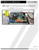
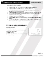
STEP 7:
SET THE DIP SWITCHES ON THE I/O BOARD
•
Set the dip switches according to the application.
•
Dip switches are used to apply specific functions to the control.
•
There are 2 sets of dip switches. A 2-position on the I/O board (DS2), and a 10-position
at the adjustment board (DS10).
Description
ON
OFF
DS2
1
Push-N-Go Hold Time
The hold time is set by TR3
potentiometer at adjustment
board
3 Seconds (Default)
2
Electric Lock Delay
500 milliseconds
200 milliseconds (Default)
Содержание SW10
Страница 11: ...920 1020 12 11 PUSH ARM ...
Страница 27: ...920 1020 12 27 SETUP BUTTON FLASHING RED LED ...
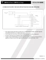
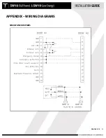
Страница 33: ...920 1020 12 33 APPENDIX WIRING DIAGRAMS SIMULTANEOUS PAIRS ...
Страница 35: ...920 1020 12 35 APPENDIX WIRING DIAGRAMS ELECTRIC LOCK APPLICATION ...
Страница 36: ...920 1020 12 36 APPENDIX WIRING DIAGRAMS SW10 PAIR WITH BEA PARALLAX SYSTEM ...
Страница 37: ...920 1020 12 37 APPENDIX WIRING DIAGRAMS SW10 Single Pair WIth BEA LZR Microscan Sensors ...
Страница 38: ...920 1020 12 38 APPENDIX WIRING DIAGRAMS SW10 Single With Push Plates Torpedo Sensors For Secondary Activation ...
Страница 42: ...920 1020 12 42 APPENDIX TUCKER LOGO ...


