920.1020.12
22
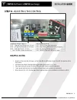
STEP 9:
ADJUSTING THE CONTROL
HELPFUL NOTES:
•
Speed and time adjustment changes will not take effect until the door closes fully after the adjustment has
been made.
•
Hold Open time affects the delay following activation from input 10, 11, and 13.
•
Opening & closing force are a function of the automatic setup and are not adjustable.
•
Check speeds and durations are a function of the automatic setup and are not adjustable.
•
When Dip Switch 5 is ON, the blue speed and time potentiometers are disabled and will have no effect.
Adjustment Board Trimmers
Adjustment Board LEDs
TR1
Opening Time Adjustment (4 – 10 secs)
LD1 GREEN LED Indicates motor power
TR2
Closing Time Adjustment (4 – 10 secs)
LD2 Rapid flashing RED indicates setup in progress
TR3
Hold Open Time (0 – 30 secs)
LD2 Slow flashing RED indicates fault
Note: Clockwise rotation increases time
LD3 GREEN LED indicates 5Vdc power supply
Содержание SW10
Страница 11: ...920 1020 12 11 PUSH ARM ...
Страница 27: ...920 1020 12 27 SETUP BUTTON FLASHING RED LED ...
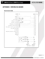
Страница 33: ...920 1020 12 33 APPENDIX WIRING DIAGRAMS SIMULTANEOUS PAIRS ...
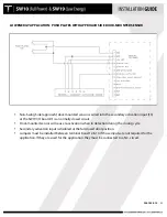
Страница 35: ...920 1020 12 35 APPENDIX WIRING DIAGRAMS ELECTRIC LOCK APPLICATION ...
Страница 36: ...920 1020 12 36 APPENDIX WIRING DIAGRAMS SW10 PAIR WITH BEA PARALLAX SYSTEM ...
Страница 37: ...920 1020 12 37 APPENDIX WIRING DIAGRAMS SW10 Single Pair WIth BEA LZR Microscan Sensors ...
Страница 38: ...920 1020 12 38 APPENDIX WIRING DIAGRAMS SW10 Single With Push Plates Torpedo Sensors For Secondary Activation ...
Страница 42: ...920 1020 12 42 APPENDIX TUCKER LOGO ...


