


Preventive maintenance
6-1
6. Preventive maintenance
This chapter describes procedures for printer preventive maintenance. Following these recommendations can
help prevent problems and maintain optimum performance.
Safety inspection guide
The purpose of this inspection guide is to aid you in identifying unsafe conditions.
If any unsafe conditions exist, find out how serious the hazard could be and if you can continue before you
correct the hazard.
Check the following items:
•
Damaged, missing, or altered parts, especially in the area of the on/off switch and the power supply.
•
Damaged, missing, or altered covers, especially in the area of the top cover and the power supply cover.
•
Possible safety exposure from any non-
Toshiba
attachments.
Lubrication specifications
No requirements for this printer.
Scheduled maintenance
Maintenance kit
The operator panel displays the message
80 Scheduled Maintenance
at each 300K page count interval. It
is necessary to replace the fuser assembly, transfer roller, charge roll, and pick tires at this interval to maintain
the print quality and reliability of the printer. The parts are available as a maintenance kit with the following part
numbers:
After replacing the kit, the maintenance count must be reset to zero to clear the “80 Scheduled Maintenance”
message. See
“Maintenance page count (Maint Cnt Value)” on page 3-25
.
Maintenance kits
Description
Part number
115 V Maintenance kit
56P4240
220 V Maintenance kit
56P4241
100 V Maintenance kit
56P4242
Содержание e-STUDIO500P
Страница 1: ...PRINTER P N 12G9609 e STUDIO500P ...
Страница 10: ...x Service Manual ...
Страница 15: ...Laser notices xv Japanese Laser Notice ...
Страница 16: ...xvi Service Manual Korean Laser Notice ...
Страница 22: ...1 2 S ervice Manual Configured model The following illustration shows a standard network printer ...
Страница 43: ...Diagnostic information 2 7 ...
Страница 159: ...Diagnostic information 2 123 ...
Страница 160: ...2 124 Service Manual ...
Страница 161: ...Diagnostic information 2 125 ...
Страница 181: ...Diagnostic aids 3 17 ...
Страница 205: ...Pages 3 42 through 3 44 have been removed from this document intentionally Diagnostic aids 3 41 ...
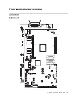
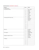
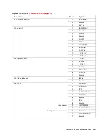
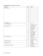
Страница 286: ...Connector locations and connections 5 1 5 Connector locations and connections Connections System board ...
Страница 297: ...5 12 Service Manual ...
Страница 298: ...Connector locations and connections 5 13 ...
Страница 299: ...5 14 Service Manual ...
Страница 301: ...6 2 Service Manual ...
Страница 303: ...7 2 Service Manual Assembly 1 Covers ...
Страница 305: ...7 4 Service Manual Assembly 2 Frame 1 ...
Страница 307: ...7 6 Service Manual Assembly 3 Frame 2 ...
Страница 309: ...7 8 Service Manual Assembly 4 Frame 3 ...
Страница 311: ...7 10 Service Manual Assembly 5 Printhead ...
Страница 313: ...7 12 Service Manual Assembly 6 Paper feed autocompensator ...
Страница 315: ...7 14 Service Manual 4061 xx0 Assembly 7 Paper feed multipurpose feeder ...
Страница 317: ...7 16 Service Manual Assembly 8 Paper feed alignment ...
Страница 319: ...Page 7 19 has been removed from this document intentionally 7 18 Service Manual ...
Страница 320: ...7 20 Service Manual Assembly 10 Integrated 500 sheet paper tray ...
Страница 322: ...7 22 Service Manual Assembly 11 Drives Main drive and developer drive ...
Страница 324: ...7 24 Service Manual Assembly 12 Hot roll fuser ...
Страница 326: ...7 26 Service Manual Assembly 13 Transfer charging ...
Страница 328: ...7 28 Service Manual Assembly 14 Electronics power supplies ...
Страница 330: ...7 30 Service Manual Note ...
Страница 332: ...7 32 Service Manual Assembly 16 Electronics shields ...
Страница 336: ...7 36 Service Manual Assembly 19 Cabling diagrams 3 ...
Страница 338: ...7 38 Service Manual Assembly 20 Cabling diagrams 4 ...
Страница 340: ...7 40 Service Manual Assembly 21 Cabling diagrams 5 ...
Страница 342: ...7 42 S ervice Manual THE FOLLOWING PAGE 7 43 HAS BEEN OMITTED FROM THIS MANUAL INTENTIONALLY ...
Страница 347: ...7 48 S ervice Manual Pages 7 49 through 7 57 of this manual have been omitted intentionally ...
Страница 348: ...7 58 Service Manual Assembly 35 High capacity feeder 1 ...
Страница 350: ...7 60 Service Manual Assembly 36 High capacity feeder 2 ...
Страница 354: ...7 64 S ervice Manual Pages 7 65 thru 7 70 ofthis manual were omitted intentionally ...
Страница 362: ...I 8 Service Manual ...
Страница 370: ...I 16 Service Manual ...


