


4-4
Service Manual
Removal procedures
CAUTION:
Remove the power cord from the printer or wall outlet before you connect or
disconnect any cable or electronic board or assembly for personal safety and to prevent damage
to the printer.
CAUTION:
Use the handholds on the side of the printer. Make sure your fingers are not under the printer when
you lift or set the printer down.
Note:
Some removal procedures require removing cable ties. You must replace cable ties during reassembly to
avoid pinching wires, obstructing the paper path, or restricting mechanical movement.
Covers removals
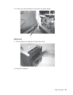
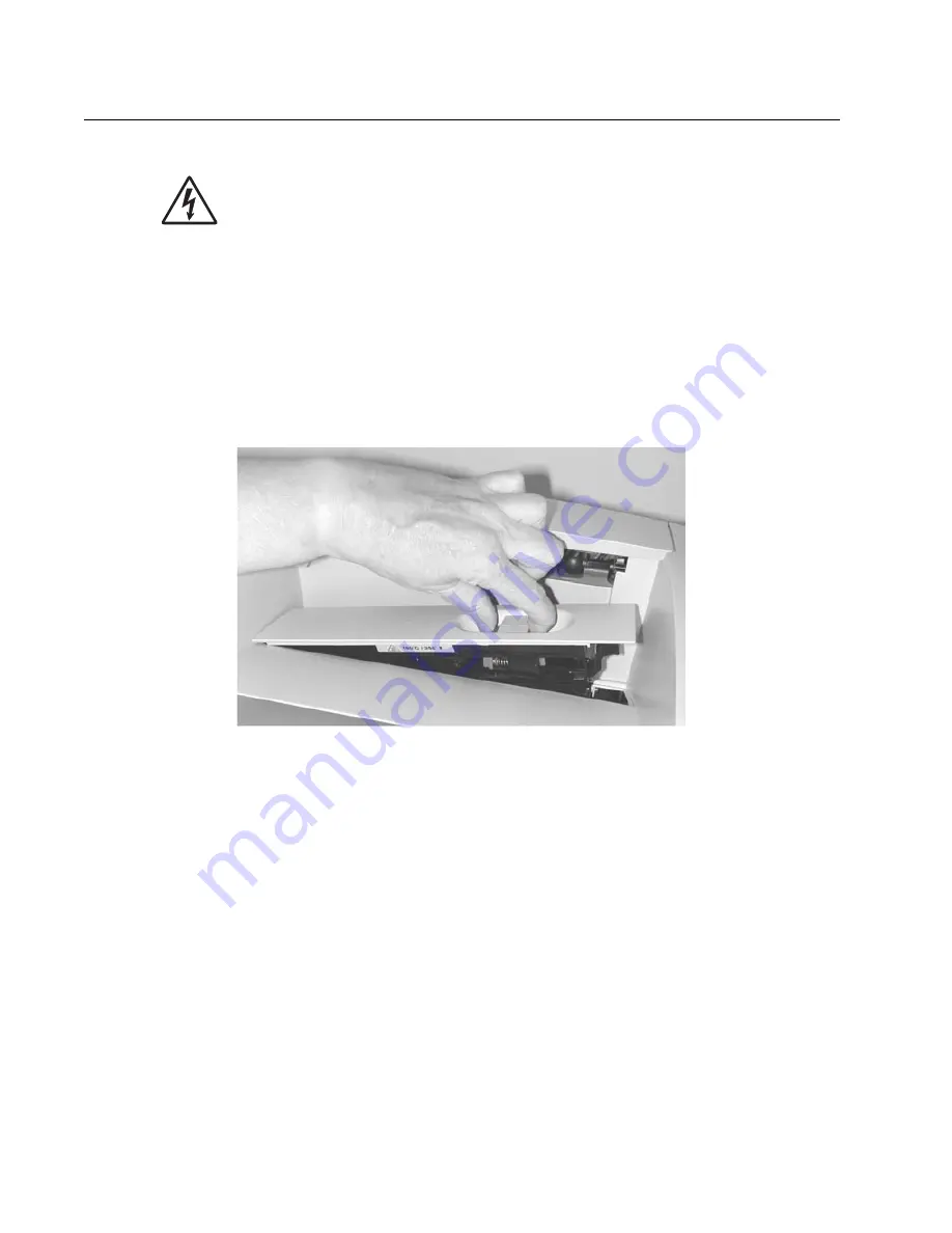
Fuser wiper cover assembly removal
1.
Squeeze the two latches together, and pull up.
2.
Remove the fuser wiper cover assembly.
Содержание e-STUDIO500P
Страница 1: ...PRINTER P N 12G9609 e STUDIO500P ...
Страница 10: ...x Service Manual ...
Страница 15: ...Laser notices xv Japanese Laser Notice ...
Страница 16: ...xvi Service Manual Korean Laser Notice ...
Страница 22: ...1 2 S ervice Manual Configured model The following illustration shows a standard network printer ...
Страница 43: ...Diagnostic information 2 7 ...
Страница 159: ...Diagnostic information 2 123 ...
Страница 160: ...2 124 Service Manual ...
Страница 161: ...Diagnostic information 2 125 ...
Страница 181: ...Diagnostic aids 3 17 ...
Страница 205: ...Pages 3 42 through 3 44 have been removed from this document intentionally Diagnostic aids 3 41 ...
Страница 286: ...Connector locations and connections 5 1 5 Connector locations and connections Connections System board ...
Страница 297: ...5 12 Service Manual ...
Страница 298: ...Connector locations and connections 5 13 ...
Страница 299: ...5 14 Service Manual ...
Страница 301: ...6 2 Service Manual ...
Страница 303: ...7 2 Service Manual Assembly 1 Covers ...
Страница 305: ...7 4 Service Manual Assembly 2 Frame 1 ...
Страница 307: ...7 6 Service Manual Assembly 3 Frame 2 ...
Страница 309: ...7 8 Service Manual Assembly 4 Frame 3 ...
Страница 311: ...7 10 Service Manual Assembly 5 Printhead ...
Страница 313: ...7 12 Service Manual Assembly 6 Paper feed autocompensator ...
Страница 315: ...7 14 Service Manual 4061 xx0 Assembly 7 Paper feed multipurpose feeder ...
Страница 317: ...7 16 Service Manual Assembly 8 Paper feed alignment ...
Страница 319: ...Page 7 19 has been removed from this document intentionally 7 18 Service Manual ...
Страница 320: ...7 20 Service Manual Assembly 10 Integrated 500 sheet paper tray ...
Страница 322: ...7 22 Service Manual Assembly 11 Drives Main drive and developer drive ...
Страница 324: ...7 24 Service Manual Assembly 12 Hot roll fuser ...
Страница 326: ...7 26 Service Manual Assembly 13 Transfer charging ...
Страница 328: ...7 28 Service Manual Assembly 14 Electronics power supplies ...
Страница 330: ...7 30 Service Manual Note ...
Страница 332: ...7 32 Service Manual Assembly 16 Electronics shields ...
Страница 336: ...7 36 Service Manual Assembly 19 Cabling diagrams 3 ...
Страница 338: ...7 38 Service Manual Assembly 20 Cabling diagrams 4 ...
Страница 340: ...7 40 Service Manual Assembly 21 Cabling diagrams 5 ...
Страница 342: ...7 42 S ervice Manual THE FOLLOWING PAGE 7 43 HAS BEEN OMITTED FROM THIS MANUAL INTENTIONALLY ...
Страница 347: ...7 48 S ervice Manual Pages 7 49 through 7 57 of this manual have been omitted intentionally ...
Страница 348: ...7 58 Service Manual Assembly 35 High capacity feeder 1 ...
Страница 350: ...7 60 Service Manual Assembly 36 High capacity feeder 2 ...
Страница 354: ...7 64 S ervice Manual Pages 7 65 thru 7 70 ofthis manual were omitted intentionally ...
Страница 362: ...I 8 Service Manual ...
Страница 370: ...I 16 Service Manual ...


