


4-2
Service Manual
Adjustment procedures
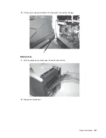
Fuser solenoid adjustment
Perform the fuser solenoid adjustment whenever you replace the fuser solenoid. Adjust the fuser solenoid while
installed in the printer. Adjust the screw on the eccentric mounted on the solenoid housing to provide an air gap
between the rear of the solenoid stator and the solenoid armature. The solenoid air gap for all models is 4.5 mm
± 0.1 mm.
Gap adjustment
The gap adjustment allows you to increase the minimum gap between sheets of paper as they are fed through
the printer. This adjustment reduces the printer overall performance, such as pages per minute, but can help in
reducing the amount of curl of some printed media, thus improving media stacking in the output bin.
1.
Enter the Diagnostic Mode.
2.
Select
Ep Setup
from the Diagnostic Menu.
3.
Select
Gap Adjust
.
4.
The range of the GAP adjustment is 0 to 255. Adjust the gap setting by using
to select the value. If
GAP=0 displays, it indicates a factory setting to minimum gap. Select a value and run several copies of the
media that displays a curl problem. It may take several tries before improvement is noticed.
Note:
This setting has no effect when duplexing.
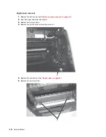
Printhead assembly adjustment
Do the printhead assembly adjustment whenever you remove or replace the printhead assembly or loosen the
mounting screws.
Install the new printhead with the three mounting screws centered in the slots in the printhead frame assembly.
Leave the screws loose enough to allow the printhead assembly to move from side to side within the slots. It is
necessary to perform a registration adjustment before locking down the three printhead mounting screws.
To perform the registration adjustment:
1.
Turn the printer off.
2.
Press and hold
and
.
3.
Turn the printer on, and release the buttons when
Performing Self Test
displays.
4.
Select
Registration
from the menu.
5.
Select
Quick Test Page
. The test page should only be printed on letter or A4 paper from Tray 1. The Quick
Test Page consists of alignment diamonds, horizontal lines that can be used for skew adjustment, page
count setting, printer serial number code levels, and print registration settings.
6.
Check the Quick Test Page for any sign of skew by checking the diamonds at the top left and top right of
the test page for equal distance from the top of the page. If necessary, adjust the left or right printhead
mounting screws and check the skew again by running another Quick Test Page. This procedure may take
two or three attempts before you get satisfactory results.
7.
When you have the correct adjustment, gently tighten the printhead mounting screws, being careful not to
move the printhead assembly.
Содержание e-STUDIO500P
Страница 1: ...PRINTER P N 12G9609 e STUDIO500P ...
Страница 10: ...x Service Manual ...
Страница 15: ...Laser notices xv Japanese Laser Notice ...
Страница 16: ...xvi Service Manual Korean Laser Notice ...
Страница 22: ...1 2 S ervice Manual Configured model The following illustration shows a standard network printer ...
Страница 43: ...Diagnostic information 2 7 ...
Страница 159: ...Diagnostic information 2 123 ...
Страница 160: ...2 124 Service Manual ...
Страница 161: ...Diagnostic information 2 125 ...
Страница 181: ...Diagnostic aids 3 17 ...
Страница 205: ...Pages 3 42 through 3 44 have been removed from this document intentionally Diagnostic aids 3 41 ...
Страница 286: ...Connector locations and connections 5 1 5 Connector locations and connections Connections System board ...
Страница 297: ...5 12 Service Manual ...
Страница 298: ...Connector locations and connections 5 13 ...
Страница 299: ...5 14 Service Manual ...
Страница 301: ...6 2 Service Manual ...
Страница 303: ...7 2 Service Manual Assembly 1 Covers ...
Страница 305: ...7 4 Service Manual Assembly 2 Frame 1 ...
Страница 307: ...7 6 Service Manual Assembly 3 Frame 2 ...
Страница 309: ...7 8 Service Manual Assembly 4 Frame 3 ...
Страница 311: ...7 10 Service Manual Assembly 5 Printhead ...
Страница 313: ...7 12 Service Manual Assembly 6 Paper feed autocompensator ...
Страница 315: ...7 14 Service Manual 4061 xx0 Assembly 7 Paper feed multipurpose feeder ...
Страница 317: ...7 16 Service Manual Assembly 8 Paper feed alignment ...
Страница 319: ...Page 7 19 has been removed from this document intentionally 7 18 Service Manual ...
Страница 320: ...7 20 Service Manual Assembly 10 Integrated 500 sheet paper tray ...
Страница 322: ...7 22 Service Manual Assembly 11 Drives Main drive and developer drive ...
Страница 324: ...7 24 Service Manual Assembly 12 Hot roll fuser ...
Страница 326: ...7 26 Service Manual Assembly 13 Transfer charging ...
Страница 328: ...7 28 Service Manual Assembly 14 Electronics power supplies ...
Страница 330: ...7 30 Service Manual Note ...
Страница 332: ...7 32 Service Manual Assembly 16 Electronics shields ...
Страница 336: ...7 36 Service Manual Assembly 19 Cabling diagrams 3 ...
Страница 338: ...7 38 Service Manual Assembly 20 Cabling diagrams 4 ...
Страница 340: ...7 40 Service Manual Assembly 21 Cabling diagrams 5 ...
Страница 342: ...7 42 S ervice Manual THE FOLLOWING PAGE 7 43 HAS BEEN OMITTED FROM THIS MANUAL INTENTIONALLY ...
Страница 347: ...7 48 S ervice Manual Pages 7 49 through 7 57 of this manual have been omitted intentionally ...
Страница 348: ...7 58 Service Manual Assembly 35 High capacity feeder 1 ...
Страница 350: ...7 60 Service Manual Assembly 36 High capacity feeder 2 ...
Страница 354: ...7 64 S ervice Manual Pages 7 65 thru 7 70 ofthis manual were omitted intentionally ...
Страница 362: ...I 8 Service Manual ...
Страница 370: ...I 16 Service Manual ...


