BAG A (Continued)
2
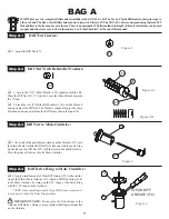
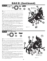
Step A-5
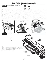
Step A-6
Figure 5
q
1. Insert a 5mm x 8mm Bearing (117) into the center of the 42T Diff
Pulley (42).
q
2. Press a 3/32" Diff Ball (82) into each of the twelve small holes
in the Diff Pulley as indicated in Figure 5.
117
82
q
1. Apply a moderate coat (continuous bead) of Clear Diff Grease
(172) to the exposed side of the Diff Ring (108) that is already at-
tached to the Male Outdrive (19).
q
2. Carefully place the Diff Pulley (42) over the post on the
Outdrive so that the Diff Balls (82) and Diff Pulley rest against the
Greased Drive Ring. Leave the assembly with the 1/16" Allen Wrench
(125) standing as shown in Figure 6.
Diff Pulley:
Diff Pulley to Male Outdrive:
82
42
117
108
42
82
CLEAR DIFF
GREASE (172)
19
Figure 6


