78
184
84
26
130
53
129
129
130
184
11
25
85
78
BAG F (Continued)
28
q
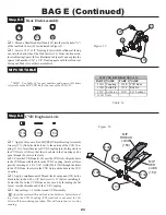
1. Position the bottom of an assembled rear Shock in front of the
Shock mounting area on the left rear suspension Arm (11) as shown
in Figure 67. Align the hole in the Shock Mount Ball (78) with the
inside hole in the Arm.
q
2. Attach the Shock to the rear Arm by threading a 4-40 x 1/2" Cap
Head Screw (129) through the Shock Mount Ball into the inside hole
of the suspension Arm.
q
3. Slide a "long" Shock Mount Bushing (25), large side first, over
the Screw (130) on the left side of the Tower.
Before attaching the top of the Shock, make sure that the drive
end of the CVD is in place in the Outdrive.
q
4. Place the top of the Shock Body (85) over the Shock Mount
Bushing. Secure the Shock to the Tower by threading a 4-40 Locknut
(184) onto the Shock Mount Screw.
q
5. Repeat Steps 1-4 for the right side rear Shock Assembly.
184
Step F-6
Rear Shock Install
Step F-7
Front Shock Install
129
Figure 67
25
129
184
26
Figure 68
q
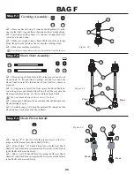
1. Position the bottom of an assembled front Shock in front of the
Shock Mounting area on the left front suspension Arm (53) as shown
in Figure 68. Align the hole in the Shock Mount Ball (78) with the
inside hole in the Arm (53).
q
2. Secure the Shock to the Arm by threading a 4-40 x 1/2" Cap
Head Screw (129) into the Arm from the front side.
q
3. Slide a "short" Shock Bushing (26), large side first, over the
Screw (130) on the left side of the front Shock Tower.
Before attaching the top of the Shock, make sure that the drive
end of the CVD is in place in the Outdrive.
q
4. Place the top of the front Shock Body (84) over the Shock
Mount Bushing on the Tower. Secure the shock assembly to the
Tower by threading a 4-40 Locknut (184) onto the Shock Mount Screw.
q
5. Repeat Steps 1-4 for the right side front Shock assembly.


