BAG E (Continued)
23
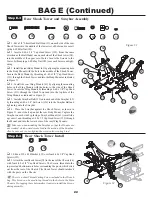
Figure 53
Figure 55
q
1. Thread a Short Head Ball Stud (107) into the inside hole ("A")
of the rear Hub Carrier (23) as indicated in Figure 53.
q
2. Insert a 3/16" x 3/8" Bearing (116) with the teflon seal facing
out, into the back-side of the Hub Carrier (23). From the front-side,
insert a Bearing Spacer (89) as illustrated in Figure 53 and capture the
spacer with another 3/16" x 3/8" Bearing again with the teflon seal
facing out. Make two of these assemblies.
Step E-5
CVD Dogbone/Axle
Step E-6
116
107
89
116
107
23
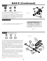
MIP CVD TABLE
Rear Hub Assembly
*NOTE: See Table 54 for part numbers and name of all items
referred to in the MIP CVD kit for the rear of the XXX-4 G+.
RED
LUBE
THREAD
LOCK
MIP
(158)
MIP
(157)
113C
113E
113B
113D
113A
113A
113B
113C
q
1. Apply a thin coat of red MIP RED Thrust Bearing/Assembly
Grease (157), (from the white tube), to the outside of the CVD Cou-
pling (113A). Insert the greased CVD Coupling into the large hole in
the CVD Axle (113D) so that the cross-hole in the Coupling can be
seen through the slots in the Axle.
q
2. Place the CVD Bone (113E) over the CVD Axle. Align the holes
in the CVD Bone with the hole in the CVD Coupling. Secure all three
parts by inserting a 1/16" x 7/16" (solid) Pin (113B) through the holes
in the CVD Bone, the slots in the CVD Axle, and the hole in the CVD
Coupling.
q
3. Apply a small amount of Thread-lock Compound (158) (in the
black tube) to the 4-40 x 1/8" Set Screw (113C) before installing it.
Center the Pin in the CVD Bone and secure it by threading the Set
Screw into the threaded end of the CVD Coupling.
q
4. Repeat Steps 1-3 for the second CVD assembly.
Apply the enclosed Thread-lock to the Set Screw before thread-
ing it into the CVD Coupling. If Thread-lock is not used, the Set
Screw will loosen during operation. This will cause your car to stop
running.
Table 54
PART # NAME
PART # NAME
113A
Coupling
113E
CVD Bone
113B
Solid Pin
113F
Roll Pin
113C
Set Screw
113G
8-32 Locknut
113D
Axle
MIP CVD KIT REAR XXX-4 G+
89

