140
18
53
BAG D (Continued)
19
Step D-7
Step D-8
Step D-9
q
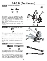
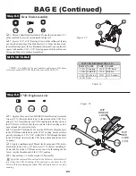
1. Attatch the Spindle (16) to the Spindle Carrier (18) by sliding
the CVD Bone (114E) through the Spindle Carrier as illustrated in
Figure 43. Line up the holes in the Spindle and the Spindle Carrier and
thread a Kingpin Screw (140) through the Spindle and into the Spindle
Carrier from the top and bottom.
q
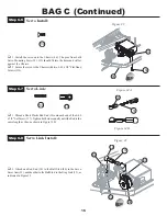
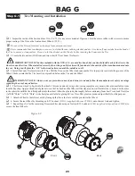
2. Thread a 4-40 x 3/8" Ball Stud (80) into the top of the left
Spindle Carrier.
q
3. Repeat Steps 1-2 for the right Spindle (15) and Spindle Carrier
(17) assembly.
q
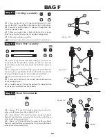
1. Thread a plastic Rod End (4) onto each end of a 1.625" Tita-
nium Turnbuckle (139). Tighten both Rod Ends equally until the Tierod
is the same length as the one in Figure 45B. Make two of these Tierod
assemblies.
The two ends of the Turnbuckle are threaded opposite. The end
closest to the groove, next to the square, has standard right-hand
threads, the other end has left-hand threads. This allows the length
of the Tierods, once installed, to be adjusted without removing them.
Front Arm to Spindle & Carrier
Spindle Carrier Assembly
4
Figure 43
Figure 45A
Figure 45B
Figure 44
80
140
140
139
140
80
16
18
114E
140
q
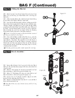
1. Attach the left Spindle Carrier assembly to the left front Arm
(53) by aligning the holes in the Spindle Carrier (18) with the holes in
the Front Arm. Thread a Kingpin Screw (140) through the outer holes
in the front and back of the Arm, and into the Spindle Carrier. Tighten
the Screws.
You may have to loosen the Screws 1/4 turn to allow free move-
ment of the Spindle Carrier on the Arm.
q
3. Repeat Step 1 for the right Arm to Spindle Carrier (17) ass-
embly.
Front Camber Tierod Assembly


