INTRODUCTION
Page-3
HOW TO USE THIS MANUAL
This manual is organized into five main sections:
INTRODUCTION
This section describes how to use this service manual
and how to identify your vehicle.
Safety Rules and Operating Instructions
This section outlines the safety and operational issues,
location and operation of controls, and the operational
checks that are to be performed on this vehicle. It
also includes various subjects that should be included
in the operator and service training program.
Maintenance Service and Repair
This section gives specific information on the servicing
of the vehicle and a schedule for maintenance checks.
Electrical and Charger Troubleshooting
This section identifies the troubleshooting procedures
for testing the electrical system and battery charger.
Illustrated Parts
This section provides an illustrated view of various
assemblies. The illustrations are accompanied by
tables identifying the parts.
Conventions
Symbols and/or words that are used to define
warnings, cautions, instructions, or notes found
throughout this manual. Refer to the examples below.
Note: Alerts the reader to additional
information about a subject.
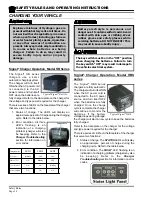
Model B 2-48 equipped
with the Dump Bed option
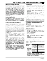
Model R 3-80 shown equiped with a cargo
box and steel cab with doors options
A shaded box with and the word “Warning”
and the symbol
above denotes a
warning. This warning alerts the reader of
a high voltage hazard that may result in
injury to themselves or others. Be sure to
follow any instructions contained within a
warning and exercise extreme care while
performing the task.
A shaded box with the word “Warning” and
the symbol
above denotes a warning. A
warning alerts the reader of a hazard that
may result in injury to themselves or
others. Be sure to follow any instructions
contained within a warning and exercise
extreme care while performing the task.
A box with the word “CAUTION” and the
symbol
above denotes a caution and is
used to inform the reader that property
damage may occur. Be sure to exercise
special care and follow any instructions
contained with in a caution.
Содержание ET-015-00
Страница 2: ......
Страница 14: ...TAYLOR DUNN...
Страница 28: ...TAYLOR DUNN...
Страница 48: ...Maintenance Service and Repair Steering Page 12 Exploded View of Steering Gear...
Страница 60: ...Maintenance Service and Repair F2 F3 Transmission Page 12 EXPLODED VIEW...
Страница 71: ...Maintenance Service and Repair Brakes Page 11 Rear Brake left side shown...
Страница 72: ...TAYLOR DUNN...
Страница 80: ...TAYLOR DUNN...
Страница 90: ...TAYLOR DUNN...
Страница 91: ...TABLE OF CONTENTS Throttle Linkage Adjustments 2 Magnetic Module 2 Pot Box module 3 Throttle Linkage...
Страница 94: ...TAYLOR DUNN...
Страница 100: ...TAYLOR DUNN...
Страница 114: ...TAYLOR DUNN...
Страница 116: ...TAYLOR DUNN...
Страница 120: ...Illustrated Parts Parts Page 4 Steering Linkage 1 2 2 2 3 4 5 5 6 4 1 7 8 9 1 1 7 7 18 4 1 1 10 11 12 13 14 15 16 17...
Страница 122: ...Illustrated Parts Parts Page 6 Steering Gear 10 9 17 16 2 3 14 15 12 11 13 6 8 7 5 4 1 Steering Column...
Страница 128: ...Illustrated Parts Parts Page 12 Transmission Differential Case Seal with 94 430 03 RTV SILICON GSKT SLR BLUE...
Страница 130: ...Illustrated Parts Parts Page 14 Rear Axle Axle tube 4 5 6 7 3 2 Rear Brakes...
Страница 132: ...Illustrated Parts Parts Page 16 Rear Suspension 1 2 3 4 5 6 7 8 9 10 11 12 13 14 Drive Shaft...
Страница 134: ...Illustrated Parts Parts Page 18 Motor direct drive Motor Mount direct drive...
Страница 140: ...Illustrated Parts Parts Page 24 Brake linkage parking brake 1 2 3 4 5 6 7 8 9 Spacer Included with 1...
Страница 142: ...Illustrated Parts Parts Page 26 Instrument Panel dash...
Страница 144: ...Illustrated Parts Parts Page 28 Speed Control Panel 1 2 3 4 5 6 7 8 9 10 11 12 4...
Страница 152: ...Illustrated Parts Parts Page 36 Charger 2 1 15 12 11 4 3 5 8 10 6 7 9 13 14 16...
Страница 156: ...Illustrated Parts Parts Page 40 Decals...


