


Maintenance, Service, and Repair
Electrical Troubleshooting
Page 7
Throttle Module:
The throttle module is located under the floorboard and functions as a throttle position sensor. The
throttle module has two output signals, one is a varying voltage relative to the pedal position and the
other is a fixed voltage indicating that the pedal is depressed.
Other than the FS-1 switch, there are no static tests for the module. To test the module, it must be
connected to a power source. To bench test the FS-1 switch, check continuity between pins #4 and
#5. Should be closed only when the pedal is depressed. If open, replace the module.
The module can be bench tested by applying 36 volts to module pins #7 (+) and #9 (-).
For this procedure, the module will be tested while in the vehicle using the 75-089-00 test harness.
Testing in the vehicle will also help in identifying certain vehicle wiring faults.
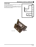
The test harness plugs into the throttle module and vehicle harness. It has a long extension with a
connector that allows for direct voltage tests to all of the wires going to and from the module. The
vehicle should not be able run while the test harness is connected.
This illustration shows the test end of the harness and the orientation
of the terminals. The terminal numbers shown are exactly as on the
test harness.
NOTE: Perform the test for Pin #9 first, then use pin #9 as the battery
negative reference for all other tests.
Pin #9, 36 Volt negative input:
> Referencing battery positive, should be full battery voltage.
If not correct, check wiring.
Pin #1, #3 , #6, #8 - Not used on this vehicle.
Pin #2, throttle position output:
> Test voltage while slowly depressing the throttle pedal. The voltage should vary
between 6 Volts (creep) and 11 Volts (full speed).
If out of range AND Pin #7 AND Pin #9 tested good, then replace the module.
Pin #4, 12 Volt input:
< Should be 12 Volts (nominal).
If not correct, check the key switch, CB1, and D1.
Pin #5. 12 Volt output (FS-1):
> With pedal UP, should be 0 Volts. With pedal depressed (any position) should be 12
Volts (nominal).
If 12 Volts with pedal up, then check module FS-1 for welded contacts or vehicle wiring for
shorts.
If not 12 Volts with the pedal depressed AND Pin #4 tested good, then replace the module.
Pin #7, +36 Volt input:
> Should be between 25 and 40 Volts with the key switch ON (ISO contactor closed).
If out of range, check resistor R, CB2, and ISO contacts.
NOTE: An incorrect voltage could also be a result of a defective module.
Содержание ET-015-00
Страница 2: ......
Страница 14: ...TAYLOR DUNN...
Страница 28: ...TAYLOR DUNN...
Страница 48: ...Maintenance Service and Repair Steering Page 12 Exploded View of Steering Gear...
Страница 60: ...Maintenance Service and Repair F2 F3 Transmission Page 12 EXPLODED VIEW...
Страница 71: ...Maintenance Service and Repair Brakes Page 11 Rear Brake left side shown...
Страница 72: ...TAYLOR DUNN...
Страница 80: ...TAYLOR DUNN...
Страница 90: ...TAYLOR DUNN...
Страница 91: ...TABLE OF CONTENTS Throttle Linkage Adjustments 2 Magnetic Module 2 Pot Box module 3 Throttle Linkage...
Страница 94: ...TAYLOR DUNN...
Страница 100: ...TAYLOR DUNN...
Страница 114: ...TAYLOR DUNN...
Страница 116: ...TAYLOR DUNN...
Страница 120: ...Illustrated Parts Parts Page 4 Steering Linkage 1 2 2 2 3 4 5 5 6 4 1 7 8 9 1 1 7 7 18 4 1 1 10 11 12 13 14 15 16 17...
Страница 122: ...Illustrated Parts Parts Page 6 Steering Gear 10 9 17 16 2 3 14 15 12 11 13 6 8 7 5 4 1 Steering Column...
Страница 128: ...Illustrated Parts Parts Page 12 Transmission Differential Case Seal with 94 430 03 RTV SILICON GSKT SLR BLUE...
Страница 130: ...Illustrated Parts Parts Page 14 Rear Axle Axle tube 4 5 6 7 3 2 Rear Brakes...
Страница 132: ...Illustrated Parts Parts Page 16 Rear Suspension 1 2 3 4 5 6 7 8 9 10 11 12 13 14 Drive Shaft...
Страница 134: ...Illustrated Parts Parts Page 18 Motor direct drive Motor Mount direct drive...
Страница 140: ...Illustrated Parts Parts Page 24 Brake linkage parking brake 1 2 3 4 5 6 7 8 9 Spacer Included with 1...
Страница 142: ...Illustrated Parts Parts Page 26 Instrument Panel dash...
Страница 144: ...Illustrated Parts Parts Page 28 Speed Control Panel 1 2 3 4 5 6 7 8 9 10 11 12 4...
Страница 152: ...Illustrated Parts Parts Page 36 Charger 2 1 15 12 11 4 3 5 8 10 6 7 9 13 14 16...
Страница 156: ...Illustrated Parts Parts Page 40 Decals...