SAFETY RULES AND OPERATING INSTRUCTIONS
Safety Rules
Page 4
VEHICLE CONTROLS
1) Light Switch
The headlight switch is located on the left dash panel.
Push the top of the switch to turn the lights on. Push the
bottom of the switch to turn the lights off.
2) Windshield Wiper Switch.
The windshield wiper switch is located on the left dash
panel. Push the top of the switch to turn the lights on.
Push the bottom of the switch to turn the light off.
3) Hour Meter.
The hour meter is located to the left of the battery status
indicator. It records the number of hours the vehicle has
been in operation.
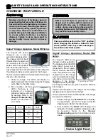
4) Battery Status Gauge
The battery status indicator is located on the left dash
panel. The battery status indicator has a LED bar graph
that indicates the relative state of charge of the battery.
The top LED will light only when connected to a fully
charged battery or after completing a charging cycle.
Successive lower LED’s will light as the battery charge
diminishes. When the second from the bottom LED
flashes the battery energy status is in energy reserve
and should be placed on charge as soon as possible.
When the two bottom LED’s are alternately flashing the
batteries are empty and the truck should be taken out of
service and charged to avoid damaging the batteries.
The BSI will reset to fully charged only after a complete
charge cycle is completed. A complete charge cycle is
defined as battery voltage exceeding 2.35 volts per cell
for a minimum of 6 minutes.
5) Turn Signal Lever.
The turn signal lever is located on the left side of the
steering column. Push the lever forward to activate the
right turn signal and pull the lever back to activate the
left turn signal.
6) Hazard Lights.
The hazard light switch is located on the left side of the
steering column. The switch is a small tab. To activate
the hazard lights, pull the tab out. To turn the hazard
lights off, push forward or pull back the directional signal
lever.
7) Speedometer
8) Start Switch.
A key-switch, located on the right center side of the
instrument panel, turns on the vehicle. Rotate the key
clockwise to turn the vehicle power on, counterclockwise
to turn the vehicle power off.
The key-switch should be in the “OFF” position whenever
the operator leaves the vehicle.
This switch is also designed to secure and disable the
vehicle. The key can only be removed when the key-
switch is in the “OFF” position.
9) Power Light.
The power light will be on when the start switch is on.
10) Heater/Defrost Timer (optional).
Set the heater timer to the desired time for the heater to
be on.
11) Heater/Defrost Switch (optional).
This switch has two positions. “HEAT” position turns on
the heater element and fan. “FAN” turns on the fan only.
NOTE: The heater requires a substantial amount of
power from he batteries. Running the heater for extended
periods will result in lower run time between charging.
Содержание ET-015-00
Страница 2: ......
Страница 14: ...TAYLOR DUNN...
Страница 28: ...TAYLOR DUNN...
Страница 48: ...Maintenance Service and Repair Steering Page 12 Exploded View of Steering Gear...
Страница 60: ...Maintenance Service and Repair F2 F3 Transmission Page 12 EXPLODED VIEW...
Страница 71: ...Maintenance Service and Repair Brakes Page 11 Rear Brake left side shown...
Страница 72: ...TAYLOR DUNN...
Страница 80: ...TAYLOR DUNN...
Страница 90: ...TAYLOR DUNN...
Страница 91: ...TABLE OF CONTENTS Throttle Linkage Adjustments 2 Magnetic Module 2 Pot Box module 3 Throttle Linkage...
Страница 94: ...TAYLOR DUNN...
Страница 100: ...TAYLOR DUNN...
Страница 114: ...TAYLOR DUNN...
Страница 116: ...TAYLOR DUNN...
Страница 120: ...Illustrated Parts Parts Page 4 Steering Linkage 1 2 2 2 3 4 5 5 6 4 1 7 8 9 1 1 7 7 18 4 1 1 10 11 12 13 14 15 16 17...
Страница 122: ...Illustrated Parts Parts Page 6 Steering Gear 10 9 17 16 2 3 14 15 12 11 13 6 8 7 5 4 1 Steering Column...
Страница 128: ...Illustrated Parts Parts Page 12 Transmission Differential Case Seal with 94 430 03 RTV SILICON GSKT SLR BLUE...
Страница 130: ...Illustrated Parts Parts Page 14 Rear Axle Axle tube 4 5 6 7 3 2 Rear Brakes...
Страница 132: ...Illustrated Parts Parts Page 16 Rear Suspension 1 2 3 4 5 6 7 8 9 10 11 12 13 14 Drive Shaft...
Страница 134: ...Illustrated Parts Parts Page 18 Motor direct drive Motor Mount direct drive...
Страница 140: ...Illustrated Parts Parts Page 24 Brake linkage parking brake 1 2 3 4 5 6 7 8 9 Spacer Included with 1...
Страница 142: ...Illustrated Parts Parts Page 26 Instrument Panel dash...
Страница 144: ...Illustrated Parts Parts Page 28 Speed Control Panel 1 2 3 4 5 6 7 8 9 10 11 12 4...
Страница 152: ...Illustrated Parts Parts Page 36 Charger 2 1 15 12 11 4 3 5 8 10 6 7 9 13 14 16...
Страница 156: ...Illustrated Parts Parts Page 40 Decals...


