Motor Service
Motor
Page 4
10. Using the continuity function of digital multi meter,
check the continuity from any one of the
commutator segments and the armature frame. If
it is not an open circuit, then the armature is
shorted and the motor must be replaced.
11. Rotate the motor bearing(s) by hand.
• The bearing should not ‘freewheel’ but should
come to a smooth stop when rapidly spun by
hand. If the bearing freewheels, then grease is
no longer present in the bearing and it must be
replaced. Refer to
Replacing the Bearings
section for information regarding replacing the
armature bearings.
• Feel for any roughness when the bearing is
rotated. If any roughness or grinding is noticed
then the bearing must be replaced. Refer to
Replacing the Bearings
section for
information regarding replacing the armature
bearings.
Assembly
NOTE: If this is an enclosed motor on a vehicle with
a Power Traction primary reduction, then it
is recommended to replace the armature
shaft seal any time the motor is
disassembled.
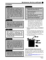
1. Push the motor brushes just far enough out of the
brush holder so that the brush springs hold them
in place away from the commutator. See the
illustration to the right.
2. Install the rear motor housing to the stator housing.
3. Lightly grease the outside diameter of the armature
bearings.
4. Insert the armature through the stator housing and
seat the bearing into the rear housing.
5. If equipped with armature retaining screws, install
and tighten them at this time.
6. If this is an enclosed motor, lightly grease the
armature shaft seal and install the front motor
housing.
NOTE: If the vehicle is equipped with a belt type
primary reduction then the spring on the
motor seal should be removed. Failure to
remove the spring may result in a high pitched
squeal from the seal.
7. Push the motor brushes into the brush holder until
the brush spring snaps into place. Be certain that
the spring does not rest up against the brush wire.
See the illustrations below.
MOTOR REMOVAL AND
INSTALLATION
See the
Transmission
section for information on
removing or installing the motor.
Содержание ET-015-00
Страница 2: ......
Страница 14: ...TAYLOR DUNN...
Страница 28: ...TAYLOR DUNN...
Страница 48: ...Maintenance Service and Repair Steering Page 12 Exploded View of Steering Gear...
Страница 60: ...Maintenance Service and Repair F2 F3 Transmission Page 12 EXPLODED VIEW...
Страница 71: ...Maintenance Service and Repair Brakes Page 11 Rear Brake left side shown...
Страница 72: ...TAYLOR DUNN...
Страница 80: ...TAYLOR DUNN...
Страница 90: ...TAYLOR DUNN...
Страница 91: ...TABLE OF CONTENTS Throttle Linkage Adjustments 2 Magnetic Module 2 Pot Box module 3 Throttle Linkage...
Страница 94: ...TAYLOR DUNN...
Страница 100: ...TAYLOR DUNN...
Страница 114: ...TAYLOR DUNN...
Страница 116: ...TAYLOR DUNN...
Страница 120: ...Illustrated Parts Parts Page 4 Steering Linkage 1 2 2 2 3 4 5 5 6 4 1 7 8 9 1 1 7 7 18 4 1 1 10 11 12 13 14 15 16 17...
Страница 122: ...Illustrated Parts Parts Page 6 Steering Gear 10 9 17 16 2 3 14 15 12 11 13 6 8 7 5 4 1 Steering Column...
Страница 128: ...Illustrated Parts Parts Page 12 Transmission Differential Case Seal with 94 430 03 RTV SILICON GSKT SLR BLUE...
Страница 130: ...Illustrated Parts Parts Page 14 Rear Axle Axle tube 4 5 6 7 3 2 Rear Brakes...
Страница 132: ...Illustrated Parts Parts Page 16 Rear Suspension 1 2 3 4 5 6 7 8 9 10 11 12 13 14 Drive Shaft...
Страница 134: ...Illustrated Parts Parts Page 18 Motor direct drive Motor Mount direct drive...
Страница 140: ...Illustrated Parts Parts Page 24 Brake linkage parking brake 1 2 3 4 5 6 7 8 9 Spacer Included with 1...
Страница 142: ...Illustrated Parts Parts Page 26 Instrument Panel dash...
Страница 144: ...Illustrated Parts Parts Page 28 Speed Control Panel 1 2 3 4 5 6 7 8 9 10 11 12 4...
Страница 152: ...Illustrated Parts Parts Page 36 Charger 2 1 15 12 11 4 3 5 8 10 6 7 9 13 14 16...
Страница 156: ...Illustrated Parts Parts Page 40 Decals...


