


Maintenance, Service, and Repair
Steering
Page 10
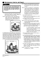
REPAIR THE STEERING GEAR
Disassembly
NOTE: The steering gear must be removed from the vehicle for this procedure. Refer to
Replace the
Steering Gear
section for information regarding removing the steering gear.
NOTE: The steering gear is packed with grease. Only perform maintenance on the steering gear in an
area that will contain any grease that may spill out of the steering gear when it is disassembled.
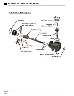
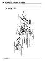
Refer to the illustration at the end of this section for a blown up view of the steering gear assembly.
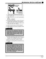
1. Center the steering gear.
A. Turn the steering shaft all of the way in one
direction.
B. While counting the rotation, turn the steering
shaft all of the way in the opposite direction.
C. Turn the steering shaft 1/2 the number of turns
in the original direction.
2. Remove the worm bearing adjuster locking ring
and the worm bearing adjuster.
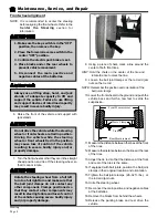
3. Remove the side cover/pitman shaft assembly by
removing the three side cover bolts and then
pulling the assembly out of the housing.
NOTE: The side cover/pitman shaft assembly
normally does not have to be disassembled.
4. Remove the worm shaft and ball nut assembly
from the bottom of the housing.
5. Remove the worm shaft seal.
6. Remove the pitman shaft seal.
7. Remove the upper worm bearing and bearing cup
from the housing.
8. The ball nut assembly consists of two sets of ball
bearings that recirculate in two channels in the
ball nut housing. The bearings may fall out once
the bearing guides are removed. Be careful not to
lose any of the bearings.
9. Remove the ball guide clamps, ball guides and all
of the ball bearings.
10. Remove the ball nut from the worm shaft.
11. Thoroughly clean and inspect all parts for signs of
corrosion, damage or wear and replace as
required.
Содержание ET-015-00
Страница 2: ......
Страница 14: ...TAYLOR DUNN...
Страница 28: ...TAYLOR DUNN...
Страница 48: ...Maintenance Service and Repair Steering Page 12 Exploded View of Steering Gear...
Страница 60: ...Maintenance Service and Repair F2 F3 Transmission Page 12 EXPLODED VIEW...
Страница 71: ...Maintenance Service and Repair Brakes Page 11 Rear Brake left side shown...
Страница 72: ...TAYLOR DUNN...
Страница 80: ...TAYLOR DUNN...
Страница 90: ...TAYLOR DUNN...
Страница 91: ...TABLE OF CONTENTS Throttle Linkage Adjustments 2 Magnetic Module 2 Pot Box module 3 Throttle Linkage...
Страница 94: ...TAYLOR DUNN...
Страница 100: ...TAYLOR DUNN...
Страница 114: ...TAYLOR DUNN...
Страница 116: ...TAYLOR DUNN...
Страница 120: ...Illustrated Parts Parts Page 4 Steering Linkage 1 2 2 2 3 4 5 5 6 4 1 7 8 9 1 1 7 7 18 4 1 1 10 11 12 13 14 15 16 17...
Страница 122: ...Illustrated Parts Parts Page 6 Steering Gear 10 9 17 16 2 3 14 15 12 11 13 6 8 7 5 4 1 Steering Column...
Страница 128: ...Illustrated Parts Parts Page 12 Transmission Differential Case Seal with 94 430 03 RTV SILICON GSKT SLR BLUE...
Страница 130: ...Illustrated Parts Parts Page 14 Rear Axle Axle tube 4 5 6 7 3 2 Rear Brakes...
Страница 132: ...Illustrated Parts Parts Page 16 Rear Suspension 1 2 3 4 5 6 7 8 9 10 11 12 13 14 Drive Shaft...
Страница 134: ...Illustrated Parts Parts Page 18 Motor direct drive Motor Mount direct drive...
Страница 140: ...Illustrated Parts Parts Page 24 Brake linkage parking brake 1 2 3 4 5 6 7 8 9 Spacer Included with 1...
Страница 142: ...Illustrated Parts Parts Page 26 Instrument Panel dash...
Страница 144: ...Illustrated Parts Parts Page 28 Speed Control Panel 1 2 3 4 5 6 7 8 9 10 11 12 4...
Страница 152: ...Illustrated Parts Parts Page 36 Charger 2 1 15 12 11 4 3 5 8 10 6 7 9 13 14 16...
Страница 156: ...Illustrated Parts Parts Page 40 Decals...