16
17
5. Coupling with Other Machines
Common
(4) Mounting Torque Arm (Option)
(1) Mount the torque arm on the driven shaft machine side of the case.
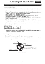
(2) Ensure there is some degree of freedom for the torque arm retainer (Figure 5-13, 5-14) so that no excessive force is applied between
the product and the driven shaft. (The retainer is to be prepared by the customer.)
(3) Never fix the torque arm using a retainer bolt.
(4) If frequent starting and stopping are expected, or for repetitious plugging operations, attach
a disk spring (see Fig. 5-12) between the torque arm and the mounting bolt (or spacer) as a
buffer material to lessen the impact.
(5) Use bolts that have a strength class of at least 10.9 (JIS B 1051).
(6) When installing the torque arm, be sure to lock the bolt.
(Use spring washers, U nuts, or apply locking adhesive.)
Part of is to be supplied by customer.
Locking part of
torque arm
Special bolt
or pin
Torque arm
Flat washer
Spacer
Make sure to have
some room
Flat washer
Special bolt
Make sure to have
some room
No freedom in
torque armʼs motion
Good Example
Bad Example
Spacer
Torque arm
Adjust the amount of the space to a size that
does not result in excessive force or contact
based on the movement of the machine.
Good Example
Torque arm and machine-side base fixed
(adhered) with no freedom of motion
The retainer bolt, machine or the prod-
uct may be damaged due to excessive
force.
Bad Example
Figure 5-13 Retainer Mounting Examples (Attachment Type Torque Arm)
Figure 5-14 Retainer Mounting Examples (Plate Type Torque Arm)
Disk spring
Figure 5-12 Disk Spring


