16
Common
5. Coupling with Other Machines
17
5-3
Hollow Shaft, Torque Arm/Flange Mounted
(1) Driven Shaft Length
When mounting the driven shaft onto the hollow shaft, make sure that the insertion length is at or above the "recommended driven
shaft length."
Refer to the catalog or consult us for more details.
(2) Mounting on the Driven Shaft
[1] Apply the molybdenum disulfide grease to the surface of the driven shaft and the hollow shaft bore and insert the product into the
driven shaft.
[2] If the fit is tight, lightly hit the end face of the hollow shaft with a wooden hammer to insert the shaft. When doing so, never hit the case
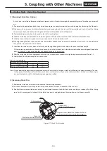
or the oil seal directly. If the fit is particularly tight, use a jig such as the one shown in Figure 5-9 for a smoother insertion.
e
c
b
a
d
トルクアーム取付1
ⓐ
Retaining ring
ⓑ
Spacer
ⓒ
Thrust bearing
ⓓ
Nut
ⓔ
Stud bolt
Figure 5-9 Mounting Jig
The hollow shaft is created with a JIS H8 tolerance. The following tolerances are recommended for driven shafts.
- If an impact does not occur when a uniform load is applied: JIS h6 or js6
- If an impact is expected or the overhung load is significant: JIS js6 or k6
- Size of retaining ring (snap ring): JI B 2804 C-ring
(3) Mounting on the Driven Shaft
If you use torque arm for retaining, be sure to fix the product onto the driven shaft.
M
achine side
M
achine side
Bearing unit
Spacer
Set screw
Stopper
End plate
Set screw
Stopper
Spacer
Retaining ring
Fixing with a Stepped Shaft
Fixing With a Set Screw And a Stopper Ring
(No Driven Shaft Step)
Fixing With a Spacer
(With No Driven Shaft Step)
Fixing with a Spacer And a Snap
Fixing With a Set Screw And a Stopper Ring
Fixing With an End Plate
Figure 5-10 Method of Fixing So That the Product Does Not Move to the Machine Side
Figure 5-11 Method of Fixing So That the Product Does Not Move in the Opposite Direction of the Machine
Notes: 1. Jigs and parts for installation or fixing are to be prepared by the customer.
2. Refer to the catalog for recommended sizes.


