18
19
5. Coupling with Other Machines
Common
5-4
Hollow Shaft, Shrink Disc Mounted
(1) Mounting Shrink Disc (Option)
A shrink disc is installed on the product before shipment, with its face for clamping bolt coated with grease. Therefore you can install
as-is.
(1) If an object is lodged between both plates while the equipment is being transported, you can dislodge it by slackening all of the bolts.
(2) When you wish to remove a shrink disc that you had used previously, and then reuse it, 1) disassemble and wash it, 2)coat the sliding
cone, fastener bolts, and the face touching the bolt head with molybdenum disulfide grease.
(3) Completely degrease the boss holes and also the shafts touching them.
(4) Slide the shrink disc over the hollow shaft. Do not tighten the fastener bolts until the driven shaft enters the hollow shaft.
(5) Slide the driven shaft or this product, and insert the driven shaft into the hollow shaft.
(6) When tightening the bolts, take care to ensure that the faces of both plates are parallel to each other. In this case, it is recommended
that you use a spanner with a short handle.
(7) Check that the shrink disc has been set correctly, and then tightening the fastener bolts with spanner of proper length.
While maintaining both plates uniformly in sequence, tighten the fastener bolts in the clockwise direction (not in diagonally opposite
pairs.) In this case, it is recommended that you tighten each bolt 30° in one turn.
(8) After the shrink disc has been tightened, be sure to use a torque wrench to obtain the tightening torque indicated in Table 5-2.
(9) Finally, check if both plates are parallel to each other.
Table 5-2 Fastener Bolts
Strength Class (JIS B 1051)
10.9
Size
M8
M10
Tightening Torque (N
・
m)
29.4
57.8
Note: Do not operate the gearmotor or speed reducer until the shrink disc has been installed by following the above procedure. The con-
tacting parts of the hollow shaft and the driven shaft are not lubricated, so if you rotate the motor when it has been installed using an
incorrect method, the shaft is liable to become damaged or scuffed.
(2) Removing Shrink Disc
(1) Remove the shrink disc in the reverse sequence to the mounting procedure.
(2) To prevent both plates from tilting on the sliding cone, slacken the bolts in sequence a little at a time.
(3) If both plates are not parallel to each other, do not attempt to remove the bolts. Both plates are likely to suddenly fly off the sliding
cone. For this reason, gently slacken all of the bolts, then insert a wedge between the two plates so that they are parallel.
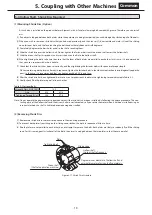
Driven shaft
(Shaft of application machine)
Tightening bolt
Plate
Sliding cone
Hollow shaft
(Output shaft of reducer)
Degrease inner diameter of hollow shaft and
external diameter of driven shaft completely.
Figure 5-17 Shrink Disc Structure


