Sample Arming 15
SR620 Universal Time Interval Counter
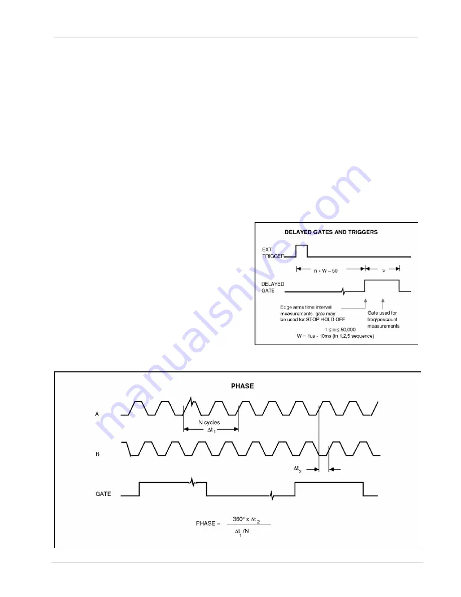
the period of the A input. Then it would make one
measurement of the time interval between A and
B. The result, 360 x (250us/1000us) = +90.0000
degrees, would be reported to the LED display.
Phase readings are always displayed between -
180 and +180 degrees.
There are two gating options in phase mode:
INTERNAL and EXTERNAL. In INTERNAL mode
the gate for the period measurement is
automatically set to 0.01s and the time interval
measurement to +time. In EXTERNAL mode the
gate time is determined by the width of a pulse
applied to the EXT input. Two pulses must be
applied to the EXT input for each complete
measurement: the first arms the time interval
measurement and the second gates the period
measurement. The external arming pulses must
be separated by at least 15 ms. Additionally, one
may use the EXT input to trigger the 1us to 10ms
scannable gates in order to measure phase as a
function of time for repetitive events.
COUNT
In this mode the unit will display the number of
events at the A or B inputs which occurred during
the gate. The gate choices are the same as for
frequency and period modes. As in the frequency
mode of operation, an internal gate may be
triggered by, or delayed relative to, the EXT input.
An event occurs when the input passes through
threshold with the selected slope. When both the
A and B source LED's are on, the ratio ( A/B ) of
events occurring on the two channels is displayed.
DELAYED ARMING MODES
In addition to the externally triggered arming
modes discussed previously, the SR620 has a
method of delayed external arming in which a user
adjustable delay is inserted between the EXT input
trigger and the arming circuitry. This delay may be
used in any of the externally triggered arming
modes. This allows one to arm a measurement at
a time other than when the external trigger arrives.
This would be useful, for example, if one wanted
to measure the frequency of an oscillator as a
function of time from a sudden change in
frequency. The signal that causes the change
would be the external trigger and by adjusting the
delay one could measure the frequency as a
function of time.
Содержание SR620
Страница 2: ...SR620 Universal Time Interval Counter...
Страница 6: ...iv Table of Contents SR620 Universal Time Interval Counter...
Страница 8: ...vi Safety and Preparation for Use SR620 Universal Time Interval Counter...
Страница 12: ...x Specifications SR620 Universal Time Interval Counter...
Страница 58: ...42 Programming Commands SR620 Universal Time Interval Counter...
Страница 72: ...56 Programming Examples SR620 Universal Time Interval Counter...
Страница 76: ...60 Troubleshooting Tips SR620 Universal Time Interval Counter...
Страница 82: ...66 Performance Test SR620 Universal Time Interval Counter...
Страница 90: ...74 Calibration Procedure SR620 Universal Time Interval Counter...
Страница 102: ...86 Circuit Description SR620 Universal Time Interval Counter...
Страница 124: ...108 Parts List SR620 Universal Time Interval Counter...


