


EyeLink II Scene Camera User Manual
©
2004-2007 SR Research Ltd.
36
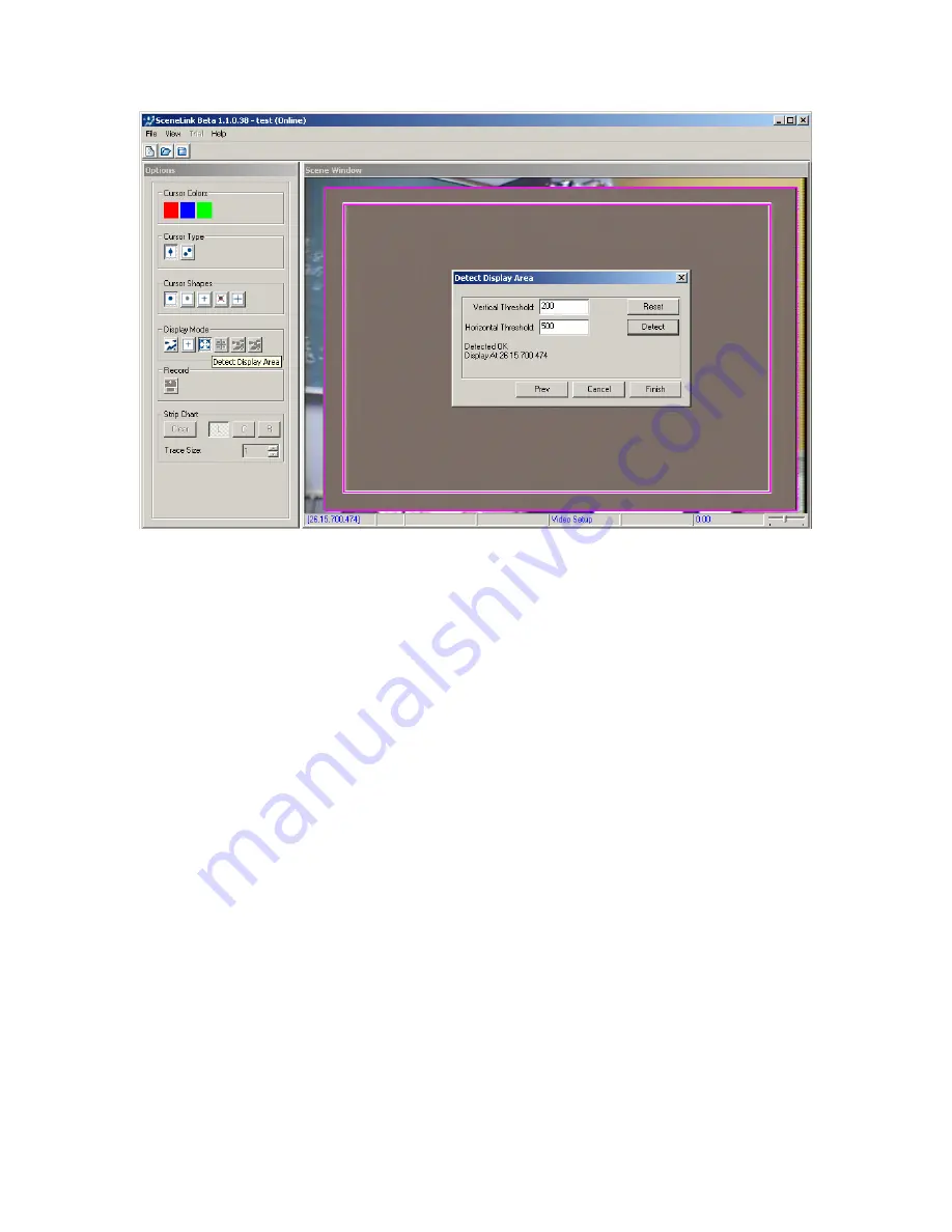
Figure
4-5. Successful Display Area Detection
The SceneLink application is now ready to use. Note that the calibration of
overlay graphics display to scene camera video needs to be done only once, as
long as the overlay and scene camera settings have not been changed.
However, the user should enter this mode to verify this at the beginning of each
recording session.
4.4 Scene Camera Alignment Mode
The optical alignment between the scene camera and head camera must be
done when the scene camera is used for the first time. By performing the
alignment, the gaze accuracy on the overlay display at the calibrated depth is
ensured. To perform the alignment:
-
From the Camera Setup Screen of the host PC, press the “Set Options”
button. In the following screen, make sure “Head Tracking” button is
enabled. Press the ENTER key to return to the previous screen.
-
On the Scene Camera Alignment screen of the host PC, first check for the
scene camera lens selection. Make sure this setting (72º or 95º field of
view) matches exactly with the actual type of lens mounted on the scene
camera bracket.
Note:
A 95º lens has a diameter of 17.0 mm measured
from the left end to right end (including the black edge); 13.5 mm
measured from the inner ring (glass part only). A 72º lens has a


