


86
MODBUS
Command Request:
<Meter Address> <Function code=04> <Register address =0> <Register
address =0>
<Register count =0> <Register count =1> <CRC high> <CRC low>
Command Response:
<Meter Address> <Function code=04> <Byte count-=2> <Status
High><Status Low>
<CRC high> <CRC low>
The MTI10/MTL10 supports only reading of the MTI10/MTL10 status. The
register address must be set to zero (Modbus Address 30001) and the
register count must be set to 1.
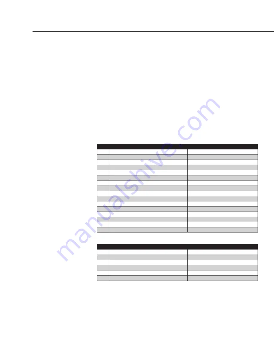
Table 6.2: Status bits definitions (Modbus Address 30001)
Bit
Definition
Comment
0
Power up indication
Reset when out of the power up sequence
1
Flow rate reached high limit threshold
Set limit to zero to disable
2
Flow rate reached low limit threshold
Set limit to zero to disable
3
Temperature reached high limit threshold
Set limit to zero to disable
4
Temperature reached low limit threshold
Set limit to zero to disable
5
Sensor reading is out of range
Check sensor wiring
6
Velocity flow rate outside of calibration table
Check sensor wiring
7
Incorrect Settings
Check settings
8
In simulation mode
Set simulation value to 0 to disable
9
Frequency output is out of range
Check frequency output settings
10
Analog 4-20 mA for flow is out of range
Check analog output settings
11
Analog 4-20 mA for temperature is out of range Check analog output settings
12
Busy
Check wiring from RS485 to Anybus IC
13
Bridge Shutdown
Check RTC
14
CRC error
Check parameters and reset CRC
15
Tot Error
Reset total
Table 6.3: Status 2 bits definitions (Modbus Address 30002)
Bit
Definition
Comment
0
CAL-V in progress
CAL-V in progress
1
ADC12<>ADC24 too far apart
Internal ADC calibration out of range
2
CAL-V Diff out of range
CAL-V Diff out of range
3
Curve #2 Selected (for 2 gas curve only)
Curve #2 Selected (2 gas curve only)
4
Zero Check Failed
Zero Check Failed
5
CAL-V/Zero Check Aborted
CAL-V/Zero Check Aborted
Protocol