PMX MANUAL
17
118164-001 REV. A
CHAPTER 3
INTERFACING
3.1
introduction
This chapter describes the interfacing of the
PMX generator to the customer system control
side, especially with the serial communication,
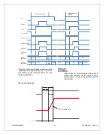
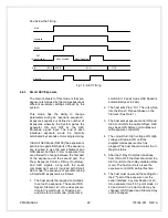
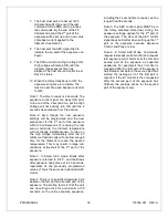
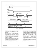
exposure control switch. Also, exposure mode
is introduced with the timing sequence
described as well.
3.2
MULTI INTERFACE
NOTE: THE INSTALLER MUST PROVIDE THE NECESSARY INTERFACING CABLES FOR WIRING TO THE
GENERATOR INPUTS AND OUTPUTS DESCRIBED IN THIS SECTION.
WARNING: LINE VOLTAGE IS PRESENT INSIDE THE GENERATOR AT ALL TIMES THAT THE MAIN
DISCONNECT IS SWITCHED ON. FOR SAFETY, THE MAIN DISCONNECT SHOULD BE
SWITCHED OFF AND LOCKED OUT WHILE CONNECTING ROOM EQUIPMENT.
3.2.1
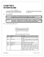
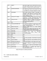
Connector Style and Pin Layout
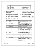
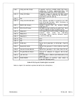
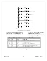
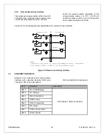
Figure 3-1 multi signal interface connector
Pin #
Definition
Description
JB1-1
GND
Generator signal ground for reference of interface
circuits
JB1-2
+5VDC Out
5 volts DC from generator for use in powering
interface circuitry such as opto couplers. 100mA
maximum.
JB1-3
RS232 Tx Out
RS232 Transmit (out) from generator
JB1-4
RS232 Rx In
RS232 Receive (in) to generator
JB1-5
PREP
User Signal (Contact Closure) to alert the
generator that exposure sequence will begin. Once
this signal is active, exposure parameters are
locked in and cannot be changed. The generator
enables the starter to boost the rotor. Contact
connection to pin 24. Closed = PREP.


