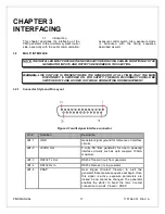
PMX MANUAL
13
118164-001 REV. A
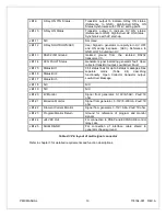
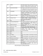
JB1-9
X-Ray ON 75% Status
Transistor output to indicate X-Ray ON status.
(Reference to GND). High/Active=X-Ray ON
Status Synchronize with 75% kV setting point.
JB1-10
X-Ray ON Status
Transistor output to indicate HV ON status.
(Reference to GND). High/Active=HV ON Status.
Synchronize with HV start-up.
JB1-11
N/C
Not Used
JB1-12
X-Ray SHUTDOWN/AEC
User Signal to generator to rapidly turn HV OFF
and ON during Exposure. (AEC). Reference to
GND. LOW Shuts down HV.
JB1-13
RS232 ISO Ground
Isolated ground from the isolated RS232
transceiver I.C.
JB1-14
HVG FAULT Status
Generator signal indicating generator fault. Open
collector transistor output. Low/Active=Fault
JB1-15
Status Bit 1
3 bit status lines for up to 6 status messages. See
separate
matrix (Table 2-4)
describing
functionality. Open Collector transistor output.
Low/Active=Message.
JB1-16
Status Bit 2
JB1-17
Status Bit 3
JB1-18
N/C
N/C
JB1-19
N/C
N/C
JB1-20
kV Monitor
Signal from generator. 0-10V=0-50kV. Zout=1K
ohm
JB1-21
Emission Monitor
Signal from generator. 0-10V=0-200mA. Zout=1K
ohm
JB1-22
Filament Current Monitor
Signal from generator. 0-10V=0-6A. Zout=1K ohm
JB1-23
Program/Monitor Return
Ground for reference of program and monitor
signals
JB1-24
+24VDC Out
For connection to PREP and EXPOSURE control
relay coils.
JB1-25
SHIELD/GND
For connection of interface cable shield to
generator chassis ground.
Table 2-3 Pin layout of multi signal connector
Refer to chapter 3 for detailed requirements and function descriptions.


