◇
46
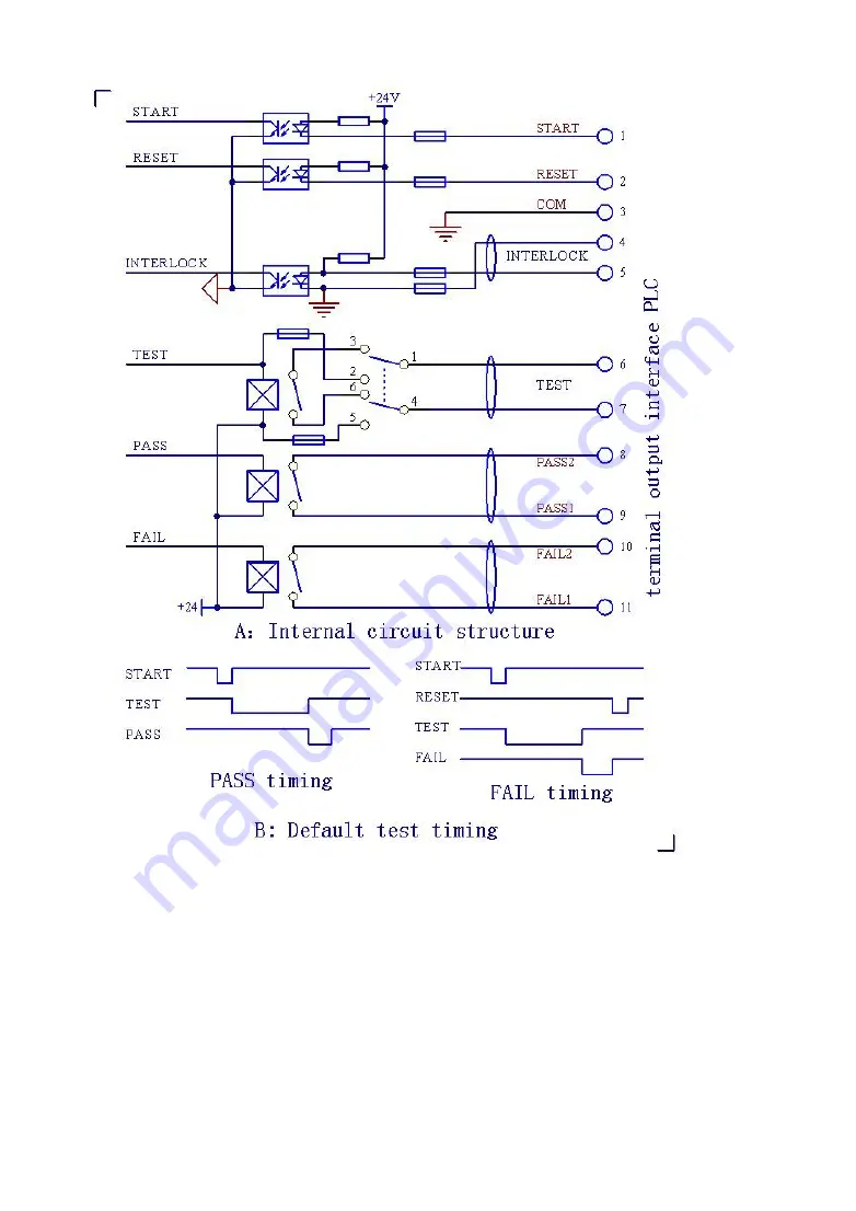
Figure 4.5.1: PLC Interface Structure and Timing
NOTE:
1.
In the TEST signal power mode Internal (switch position to the right,
battery symbol), the PLC interface can output signals of 24V, where the
real internal resistance is about 20Ω and the drive current is less than
30mA. Therefore, above signals can only be applied to drive miniwatt
components like LED. DO NOT use this signal to drive other charged
components as to avoid damaging the internal power source.
2.
If the connected current is greater than 10mA, use the external power


